Workflow: Creating a safety-relevant application or library for this application
This article contains a
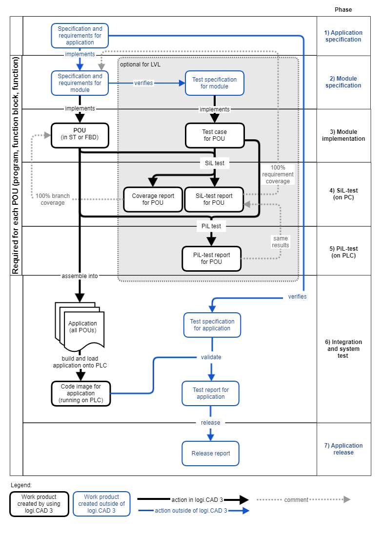
diagram showing the high-level workflow of creating a safety-relevant application when using
logi.CAD 3
. A brief explanation is given in the subsequent table specifying links for more information.
Moreover, this article and the articles s
pecified in the subsequent table (all are a part of "Safety instructions on working with the IDE") contain the safety instructions for the workflow phases that you must observe.![]() The documentation "Safety instructions on working with the IDE
"
is valid for logi.CAD 3 version 3.23.2 incl. possibly existing patch versions.
The documentation "Safety instructions on working with the IDE
"
is valid for logi.CAD 3 version 3.23.2 incl. possibly existing patch versions.
F
or the specified workflow, comply with the following warnings/notes and the warnings/notes as specified in the linked articles:
Overview of the workflow
For simplicity reasons, the diagram focuses on the workflow phases that must be applied when developing a safety-relevant application. See the subsequent table for details which workflow phase must be applied when creating a library for a safety-relevant application.
![]() The maintenance/update procedure for
logi.CAD 3
is to be done by the system integrator only.
The maintenance/update procedure for
logi.CAD 3
is to be done by the system integrator only.
Phases and work products
![]() If you are using the LVL-workflow (see "→LVL - Limited Variability Language"), actions and associated work products can be omitted. Details on this LVL-workflow and its conditions: See "Recommendations for LVL-workflow"
.
If you are using the LVL-workflow (see "→LVL - Limited Variability Language"), actions and associated work products can be omitted. Details on this LVL-workflow and its conditions: See "Recommendations for LVL-workflow"
.
When all actions are executed and all associated work products are generated, the full workflow is applied. This full workflow is also identifed as →FVL-workflow.
|
Phase |
Explanation |
Work product |
|
Application specification |
In the phase "application specification",
This is not done in logi.CAD 3 .
|
Specification and requirements for application |
|
Module specification |
In the phase "module specification",
This is not done in logi.CAD 3 .
|
Specification and requirements for module |
|
In parallel, the test specification for the module is created to verify that the module implementation complies with the module specification and fulfills the module requirements. This is not done in logi.CAD 3 .
|
Test specification for POU |
|
|
Module implementation |
In the phase "module implementation", the individual modules are developed in accordance with the specification and requirements for the module.
See "Implementing the POUs".
|
POU (in ST or FBD) |
|
Parallelly with the implementation of the POUs, a test case for each POU provides evidence that the created POU complies with the existing requirements and that its implementation contains neither undesired functionalities nor undesired properties. See "Implementing the test cases for POUs".
|
Test case for POU |
|
|
SiL-Test (on PC) |
In the phase "SiL-test (on PC)", the →SiL-test incl. coverage is executed in logi.CAD 3 for each POU on the PC verifying that the POU fulfills its specification and requirements in the simulated environment. The SiL-test incl. coverages generates a coverage report for the POU. This coverage report is proving all branches in the implementation are covered by the test. This is a condition for operating a safety application. See "SiL-test: Testing the POUs on the PC".
|
Coverage report for POU |
|
In parallel, a SiL-test report is generated for each POU. This SiL-test report is proving that all requirement are verified by the test. This is also a condition for operating a safety application. See "SiL-test: Testing the POUs on the PC".
|
SiL-test report for POU |
|
|
PiL-Test (on PLC) |
In the phase "PiL-test (on PLC)", the →PiL-test is executed in logi.CAD 3 for each POU on the actual PLC again verifying that the POU fulfills its specification and requirements when executed in the target environment. The PiL-test generates a PiL-test report for the POU. This PiL-test report is proving that all requirement are verified by the test on the actual PLC. By comparing the SiL-test report with the PiL-test report, it is ensured that the implementation behaves identical in the simulated environment and in the target environment. This is also a condition for operating a safety application. See "PiL-test: Testing the POUs on the PLC"
|
PiL-test report for POU |
|
Integration and system test |
In the phase "integration and system test", the application (with all POUs) is built in
logi.CAD 3
and then loaded on the PLC. This results in the code image for the application that is running on the PLC. See "Building and loading the application onto the PLC".
|
Code image for application (running on PLC) |
|
The application running on the PLC is validated based on the test specification for the application. This validation must be documented by a test report for the application.
The integration and system tests are required to provide evidence that the application
The validation is not done in logi.CAD 3 . However, some features or logi.CAD 3 (such as the Values of Variables view) may be used to support the validation. See "Validating the application running on the PLC".
|
Test specification for application |
|
|
Application release |
In the phase "application release", the application is released for safe operation – if all previous verification and validation stages have successfully passed.
The release must be documented by a release report. It is recommended that the fingerprint of the application is included in the release report to allow identification of the released application. See "Releasing the application for safe operation".
|
Release report |