The automatic line routing is ambiguously displaying the logic
Symptom:
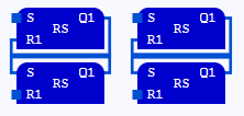
If you connect FBD-elements by lines, orthogonal lines are created by the automatic routing of lines. It is possible that the logic is ambiguously displayed.
Example: The following networks look identical to each other although they are not:
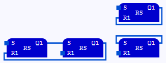
Solution 1:
Move the FBD-elements so that the networks look different.
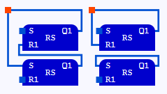
Solution2:
Create a connection point on a line and move this connection point while pressing and holding the Alt-key. Subsequently. the line is routed differently.
![]() logi.cals
recommends to install and use the most current versions of
logi.CAD 3
and the runtime system so that the latest features and problem fixes
according to the
release notes are provided in the used version.
logi.cals
recommends to install and use the most current versions of
logi.CAD 3
and the runtime system so that the latest features and problem fixes
according to the
release notes are provided in the used version.
Did this article help you? Did you find the requested information in this user documentation?
If not, contact the support team of logi.cals. State your questions or suggestions to improve/enhance the user documentation as detailed as possible.