Smart styling for the FBD-editor
Neuron Power Engineer provides 2 different styling possibilities:
-
Legacy styling: This is the default styling, if you or the system integrator have not changed anything for your system.
The illustrations included in the IDE documentation use the legacy styling (if not otherwise announced). -
Smart styling is an alternative to the legacy styling.
Usually, the smart styling is activated by a system integrator because the configuration variable
-Dlc3.editorstyle.smart.defaultmust be defined.This topic contains illustrations using the smart styling.
| In this article: |
|---|
The main advantages of the smart styling
-
The FBD elements have a more modern display to create a more visually appealing appearance.
-
The appearance is less colorful while a clear visual differentiation of different →data types is retained. As a consequence, it is easier to distinguish the safe and non-safe data types, →function blocks, and →functions.
See "Color and style for FBD-elements determined by data type" for details on how the color for the data types. -
Block inputs can only be positioned on to the left block edge while outputs can only be positioned to the right block edge.
-
The function blocks and functions provide more space to automatically display the value of variables for the inputs/outputs of the function block and function.
Likewise, →value fields (containing a variable) automatically display the value of the variable whereas value fields containing →expressions or →literals do not display the value. -
The values are displayed on top of the block inputs/outputs or on top of the value field, if FBD-editor has been opened with an →instance context. In case of longer values, the value is truncated and
...indicates the truncated value.
You cannot delete, move, or resize this "variable value display" on top of the inputs/outputs or value fields. This is an alternative to placing →OLT fields for these FBD elements. -
You can change the value of the variable by double-clicking this variable value display and entering the new value in the dialog. This dialog is identical to the one you are using to change the values within the Values of Variables view. Details: see "Changing the values of variables: writing values to PLC".
This dialog also opens when double-clicking the value field with a variable value display and an input/output of a function block. But the dialog does not open when double-clicking an input/output of a function or even a variable value display for a function. -
You are still able to insert and use the OLT fields as known from legacy styling. If you use such an OLT-field for a value field, this value field does not provide the automatic variable value display.
Using 2 different themes for smart styling
The smart styling supports a light theme as well as a dark theme. Both themes are provided in the preferences of Neuron Power Engineer.
The light theme is the default theme for smart styling.
How to change the theme to the dark theme:
-
In menu Window, select Preferences.
-
In the dialog, expand the group General and select the group Appearance.
-
Make sure that Enable theming is checked, select the theme Dark and and click Apply and Close.
-
Confirm the dialog that a restart is required by clicking Restart.
If you want to change the dark theme to the light theme, repeat these steps but select the theme Light.![]() Neuron recommends to use just the light or dark theme for smart styling. If you select other themes in smart styling apart from dark theme, the light theme will be applied.
Neuron recommends to use just the light or dark theme for smart styling. If you select other themes in smart styling apart from dark theme, the light theme will be applied.
Restrictions on changing the styling
|
Restrictions If the styling is changed from legacy to smart styling (or vice versa), observe that:
Moreover, observe that copying and pasting FBD-elements between legacy and smart styling (or vice versa) might not correctly convert the pasted FBD-elements to the target style. In such a case, you must take care to adjust the pasted FBD-elements yourself. |
These restrictions do not apply when changing the theme from light to dark (or vice versa) in the preferences.
Examples for the styling and themes
This is a counter logic with legacy styling:

This is the same counter logic but with smart styling, light theme:

This is the same counter logic but with smart styling, dark theme:

Representation of the FBD-elements for smart styling (light and dark theme)
The following illustrations focus on the main aspects of the FBD-element and how they are represented for smart styling.
If you need information on a detail for the FBD-element (e.g. how to display/hide an aspect of the FBD-element), the best practice is to follow the links in the headers to go to the description of the relevant FBD-element. There, you find more details on this FBD-elements and a list of actions for this FBD-element.
Representation of functions or function blocks
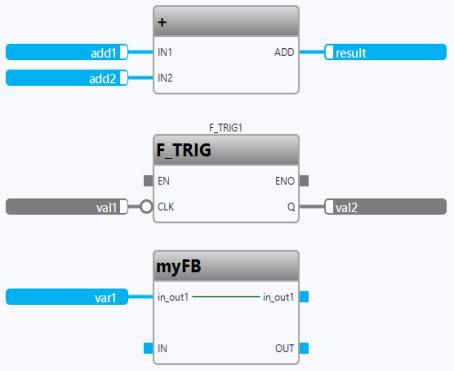
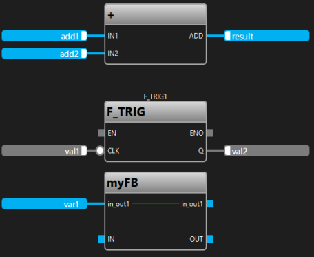
The following illustration shows 3 calls of functions or function blocks with connected value fields:
| Light theme | Dark theme |
|---|---|
|
|
Explanation:
-
The
ADDblock is connected to value fields. TheENinput andENOoutput is not shown. -
For the
F_TRIGblock, theENinput andENOoutput are shown but they are not connected. Here, the instance nameF_TRIG1is shown. The inputCLKis negated. -
The
myFBblock contains the →in-/out variablein_out1.
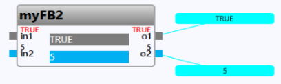
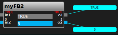
The following illustration shows a call of a function block with value fields in the interface for this block as well as OLT-fields created for the block outputs:
| Light theme | Dark theme |
|---|---|
|
|
Explanation: As the application has been loaded onto the PLC and an instance context has been set for the FBD-object, the following applies:
-
The inputs and outputs of the block display a value on top of the inputs/outputs.
-
The OLT-fields display a value.
Representation of value fields
The following illustration shows 3 values fields. Here, the value for In1 is assigned to Var1 and further to Out1:
| Light theme |

|
| Dark theme |

|
Explanation: The label within the value field inform you about the variable section the entered variable belongs. These labels are the same as the ones in the legacy styling.
Representation of comment fields
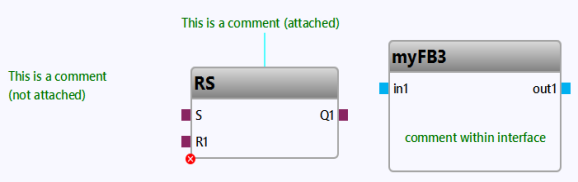
The following illustration shows 3 different kinds of comment fields:
| Light theme |
|
| Dark theme |
|
Explanation:
-
The left comment field is a default comment field that has been created for the drawing field.
-
The middle comment field is an attached comment field that has been created for the
RSblock. -
The right comment field has been created in the interface editor when designing the interface for the
myFB3block.
Regarding the dark theme: Observe that the color for the text in the comment field has manually been changed in the interface editor to have a better contrast. The different color for the text has not automatically applied by just switching to the dark theme.
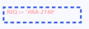
Representation of property fields
The following illustration shows a selected property field:
| Light theme | Dark theme |
|---|---|
|
|
Representation of lines and connection points
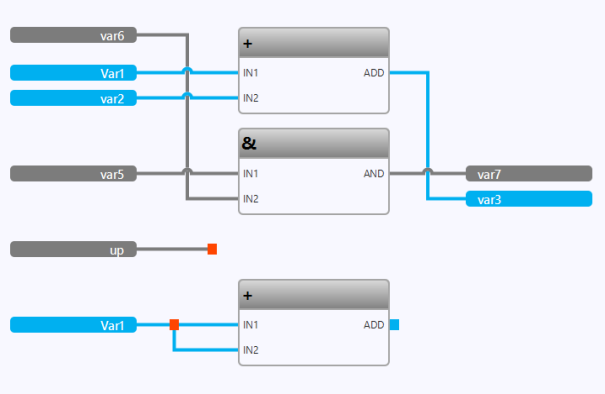
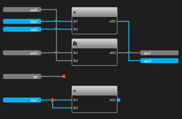
The following illustration shows different types of line connections:
| Light theme |
|
| Dark theme |
|
Explanation:
-
The upper logic (starting with the values fields
var6,Var1,var2andvar5) shows automatically routed lines connecting values fields and calls. -
The logic in the middle (with the value field
up) only shows an open line with a connection point. -
The bottom logic (starting with the value field
Var1) shows a line fork with a connection point.
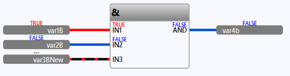
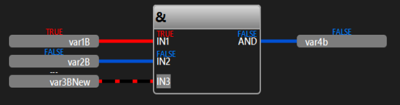
The following illustration shows how Boolean lines are emphasized within an FBD-editor with →instance context:
| Light theme |
|
| Dark theme |
|
Explanation: The Boolean lines are displayed as in the legacy styling. ![]() These illustrations also illustrates the variable value display on top of the value fields and on top of the block inputs/outputs. Observe that no value is available for
These illustrations also illustrates the variable value display on top of the value fields and on top of the block inputs/outputs. Observe that no value is available for var3BNew as it is identified by --- on top of the value field and on top of the block input IN3.
Representation of connectors and continuations
The following illustration shows an example for assigning a value for In1 to Out1 via connector/continuation C1:
| Light theme |

|
| Dark theme |

|
Representation of OLT-fields
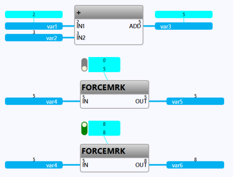
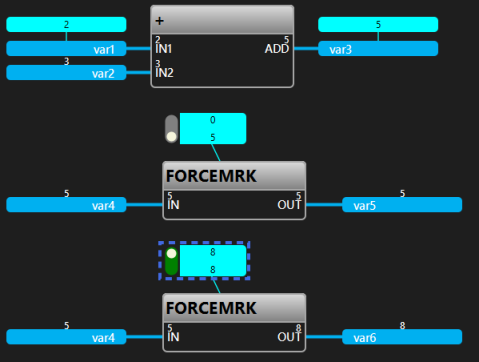
The following illustration shows 2 different types of OLT-fields:
| Light theme | Dark theme |
|---|---|
|
|
Explanation: As the application has been loaded onto the PLC and an instance context has been set for the FBD-object, the OLT-fields display a value.
Also, the inputs and outputs of the blocks display a value on top of the inputs/outputs. The value field containing var2, var4, var5 and var6 display a value on top of the value field as well because no OLT-field has been created for these value fields.
But back to the OLT-fields:
-
The logic with the
ADDblock contains 2 OLT-fields that are associated to value field containingvar1andvar3respectively. -
The remaining logic contains an OLT-field that is associated to one
FORCEMRKblock each. This type of OLT-field provides a force switch (a slider) to determine which value is written to the PLC.
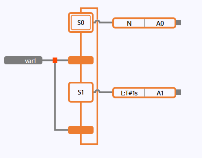
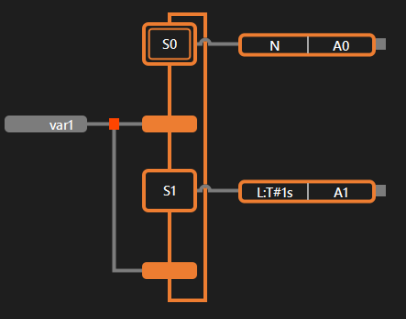
Representation of SFC-elements
The following illustration shows the initial step S0, the step S1, 2 transitions and 2 action blocks containing the action name A0 and A1 respectively:
| Light theme | Dark theme |
|---|---|
|
|
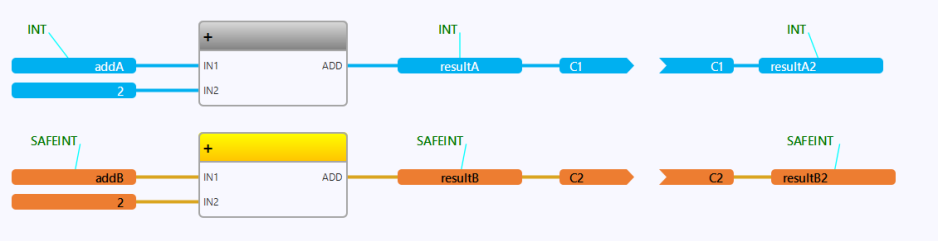
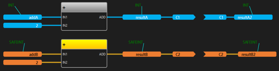
Representation of non-safe logic vs. safe logic
The following illustration shows the different representation of non-safe logic and safe logic when using the same ADD block:
| Light theme |
|
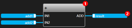
| Dark theme |
|
Explanation: Attached comment fields on top of the value fields inform about the used data types INT and SAFEINT. The value fields, the connectors and continuations are displayed with the color of the relevant data type.
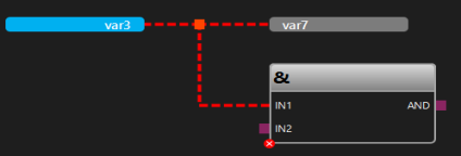
Representation of errors
The following illustration shows the highlighting of errors:
| Light theme | Dark theme |
|---|---|
|
|
|
Explanation:
-
The line is highlighted as faulty (= a red dashed line).
-
The
ANDblock is highlight as faulty as well.
Representation of other elements
-
When showing the execution order, the number is displayed within a red circle.
Light theme Dark theme 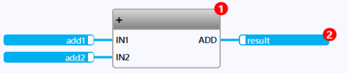
-
As in the legacy styling: The icon
 informs that a →breakpoint has been set.
Light theme Dark theme 
-
As in the legacy styling: The icons
 or
or  informs about the test coverage of a call.
Light theme Dark theme