Lines
A line connects FBD-elements, such as →value fields, with other FBD-elements.
Usually, a line leads from the output connection point (short: output) of one FBD-element to the input connection point (short: input) of the other FBD-element. Open lines are possible – an open line is a line that does not start and/or end with an FBD-element.
A line might consist of different orthogonal parts that are automatically created.
Representation
Color/style of a line is determined by the data type that is valid for the output.
![]() Depending on the configuration of your Neuron Power Engineer version, the FBD-editor and its elements might be displayed differently in your Neuron Power Engineer version than illustrated in the IDE documentation. This is the case, if Neuron or the system integrator has activated the smart styling or one of them has changed the styles for the FBD-editor. Subsequently, the illustration in the IDE documentation are symbolic images and the representation in your Neuron Power Engineer version takes precedence for the valid representation. In case of doubts, please contact Neuron or your system integrator.
Depending on the configuration of your Neuron Power Engineer version, the FBD-editor and its elements might be displayed differently in your Neuron Power Engineer version than illustrated in the IDE documentation. This is the case, if Neuron or the system integrator has activated the smart styling or one of them has changed the styles for the FBD-editor. Subsequently, the illustration in the IDE documentation are symbolic images and the representation in your Neuron Power Engineer version takes precedence for the valid representation. In case of doubts, please contact Neuron or your system integrator.
Neuron recommends that you and/or your system integrator do not use yellow shades when designing FBD-elements because the color "Yellow" is used for tracking safe signals when developing safety-related applications. This recommendation applies in particular when you are using the legacy styling. Neuron Power Engineer does not check if colors are already used elsewhere. So the use of the yellow shades by you and/or your system integrator could have the consequence that "yellow" might also identify a non-safe logic as well.
Examples for the representation:
-
Values fields that are connected with a line:

-
Calls and values fields that are connected with lines:
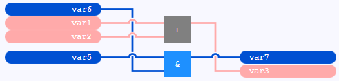
-
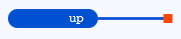
Value field with an open line:
By default, Boolean lines are emphasized within an FBD-editor with →instance context:
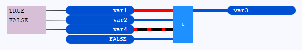
Boolean lines are lines that are connected to FBD-elements containing or representing a →variable of →data type BOOL. or a →Boolean literal. The emphasizing of Boolean lines has the following meaning:
-
A thick, red line indicates the value
TRUE(or an equivalent). -
A thick, dark-blue line indicates the value
FALSE(or an equivalent). -
A thick line dashed in black and red is indicating that no value could be requested for the line. A possible reason for this is that the current state of the application has not been loaded onto the PLC yet. This means for the illustration:: The variables
var1,var2andvar3already exist on the PLC, but not the variablevar4.
| Good to know |
|---|
|
|
 When animating a Boolean line for a variable,
 Actions for lines
Connecting an already connected line to a different FBD-element
Connecting FBD-elements by lines
Creating a line fork (incl. a connection point)
Deleting FBD-elements or already declared variables
Inserting a call of a block or value field into existing lines
![]() You might want to use connectors and continuations to replace some of the lines.
You might want to use connectors and continuations to replace some of the lines.