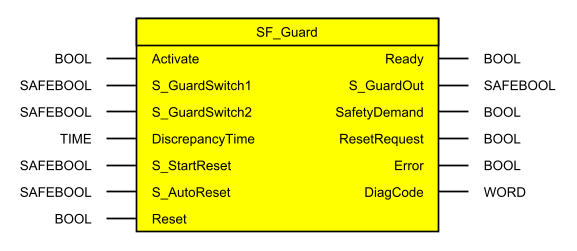
SF_Guard block
Function block
This function block monitors the respective protective equipment. There are 2 independent input parameters for 2 switches on the protective equipment coupled with a time difference ( DiscrepancyTime ) for closing the protective equipment.
Interface
|
I/O |
Name |
Data type |
Initial value |
Description |
|
IN |
Activate |
BOOL |
FALSE |
|
|
IN |
S_GuardSwitch1 |
SAFEBOOL |
SAFEFALSE |
Variable. Input circuit breaker 1. SAFEFALSE: Protective equipment open. SAFETRUE: Protective equipment closed. |
|
IN |
S_GuardSwitch2 |
SAFEBOOL |
SAFEFALSE |
Variable. Input circuit breaker 2. SAFEFALSE: Protective equipment open. SAFETRUE: Protective equipment closed. |
|
IN |
DiscrepancyTime |
TIME |
#0ms |
Constant. Configures the monitored synchronous time between S_GuardSwitch1 and S_GuardSwitch2. |
|
IN |
S_StartReset |
SAFEBOOL |
SAFEFALSE |
|
|
IN |
S_AutoReset |
SAFEBOOL |
SAFEFALSE |
|
|
IN |
Reset |
BOOL |
FALSE |
|
|
OUT |
Ready |
BOOL |
FALSE |
|
|
OUT |
S_GuardOut |
SAFEBOOL |
SAFEFALSE |
Output indicates the closed protective equipment and the protected area monitored. SAFEFALSE: Protective equipment open. SAFETRUE: Both S_GuardSwitches are SAFETRUE, no error and confirmation. Protective equipment closed. |
|
OUT |
SafetyDemand |
BOOL |
FALSE |
|
|
OUT |
ResetRequest |
BOOL |
FALSE |
|
|
OUT |
Error |
BOOL |
FALSE |
|
|
OUT |
DiagCode |
WORD |
16#0000 |
Function description
Function block SF_Guard is used to support function "protective equipment without guard locking" (safety gate monitoring) in an application.
This function block is a safety-related function block for monitoring protective equipment with a 2-stage interlocking device.
Opening the protective equipment
If the protective equipment properly connected to the function block is opened, the function block sets enable output S_Guard to SAFEFALSE (safe state).
Closing the protective equipment
If opened protective equipment in the application is closed, the function block can optionally (see Start interlock ) ensure within the safe control system that the release signal is not set to SAFETRUE solely by this closing. This requires another manual action on input parameter Reset (see Start interlock ).
Interlocking device
The function block fully supports a 2-stage interlocking device.
On a 3-stage interlocking device, the function block supports the transition from the second to the third stage and back again. On a 4-stage interlocking device, the function block supports the transition from the third to the fourth stage and back again. All other stages must be implemented in the safety application.
Guard locking device
The protective equipment's guard locking device should be programmed in a separate safety function block or in the safety application since this function block simply grants or revokes its approval. Maintaining the approval in conjunction with the guard locking device and standstill monitoring must be viewed in close connection with the safety application.
Application with 1 position switch
1 position switch (1-channel)
If 1 position switch (1-channel) is used in the protective equipment, the signal must be connected to the function block input parameter S_GuardSwitch1 over a safe input device. In addition, a graphic connection between both input parameters ("S_GuardSwitch1" and "S_GuardSwitch2") must be established in the safety application. This allows both signal inputs to be controlled by the same signal.
The function block enable output is only set to SAFETRUE if both input parameters (S_GuardSwitch1 and S_GuardSwitch2) indicate state SAFETRUE and the remaining input signal combination is valid for this as well.
1 position switch (2-channel)
If 1 position switch (2-channel) is used in the protective equipment, the signals must be connected to a safe input device individually. In the safety application, the signals of the position switch must be checked for dual-channel redundancy (e.g. using safe devices or other function blocks such as SF_Antivalent of SF_Equivalent). The signal resulting from this check be connected to function block input parameter "S_GuardSwitch1". In addition, a graphic connection between both input parameters ("S_GuardSwitch1" and "S_GuardSwitch2") must be established in the safety application. This allows both signal inputs to be controlled by the same signal.
The function block enable output is only set to SAFETRUE if both input parameters (S_GuardSwitch1 and S_GuardSwitch2) indicate state SAFETRUE and the remaining input signal combination is valid for this as well.
Application with 2 position switches
2 position switches (1-channel)
If 2 position switches (1-channel) are used in the protective equipment, the signals must be connected to one or more safe input devices individually. One of these signals must be connected to input parameter S_GuardSwitch1 of the function block. The other signal must be connected to the second function block input parameter S_GuardSwitch2.
The function block enable output is only set to SAFETRUE if both input parameters (S_GuardSwitch1 and S_GuardSwitch2) indicate state SAFETRUE and the remaining input signal combination is valid for this as well.
2 position switches (2-channel)
If 2 position switches (2-channel) are used in the protective equipment, the 4 signals must be connected to one or more safe input devices individually. In the safety application, each signal of the position switch must be checked for dual-channel redundancy (e.g. using safe devices or other function blocks such as SF_Antivalent of SF_Equivalent). A signal must result from this check for each of the 2 position switches. One of these signals must be connected to input parameter S_GuardSwitch1 of the function block. The other signal must be connected to the second function block input parameter S_GuardSwitch2.
The function block enable output is only set to SAFETRUE if both input parameters (S_GuardSwitch1 and S_GuardSwitch2) indicate state SAFETRUE and the remaining input signal combination is valid for this as well.
Quantity and layout of supported position switches
The function block supports protective equipment with 1 or 2 mechanical or non-mechanical position switches. Depending on the CAT or SIL requirements, 1-channel or 2-channel position switches with equivalent or antivalent arrangement of switching contacts are required.
The function block processes one signal per position switch, which results from checking the dual-channel redundancy on 2-channel position switches.
The function block does not monitor the dual-channel redundancy (line control) or equivalence/antivalence of the signals. This monitoring must be implemented in the safety application using safe devices or other function blocks (SF_Antivalent or SF_Equivalent), for example.
Additional information
Typical timing diagrams
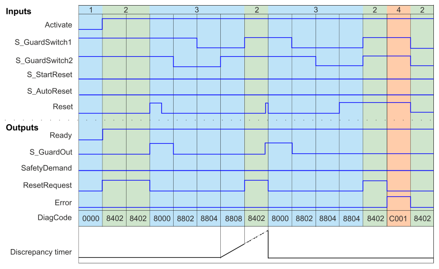
1) Start
2) Wait
3) Normal operation
4) Error
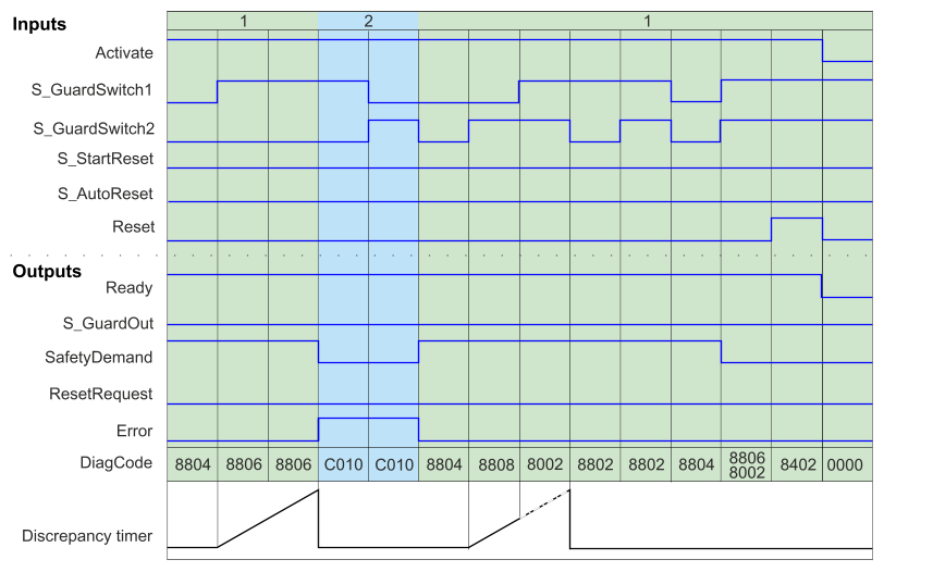
1) Normal operation
2) Error
Error detection
External signals: SAFEBOOL inputs provide inherent error detection. The mechanical structure combines the opening and closing switch according to EN 954 (protective equipment with two switches). Discrepancy-time monitoring for time delay between the reaction of both mechanical switches according to EN 954 (considered as "application fault" detection, i.e. generated by the application).
An error is detected if the time delay between the first input S_GuardSwitch1/S_GuardSwitch2 and the second is greater than the value for input DiscrepancyTime. The output Error is set to TRUE.
The function block detects a static TRUE signal on input Reset.
Error behavior
Output S_GuardOut is set to FALSE . If the two inputs S_GuardSwitch1 and S_Guardswitch2 are bridged, no error is detected. Input Reset must be set to FALSE to exit the error state Reset . To leave the discrepancy time errors, inputs S_GuardSwitch1 and S_GuardSwitch2 must both be set to FALSE .
Error and status messages
Function block specific error codes
|
DiagCode |
Name |
Description and output settings |
|
C001 |
Reset error |
Static reset detected in status 8402. Ready = TRUE S_GuardOut = SAFEFALSE SafetyDemand = FALSE ResetRequest = FALSE Error = TRUE |
|
C010 |
Discrepancy time error 1 |
Discrepancy time in state 8806 has expired. Ready = TRUE S_GuardOut = SAFEFALSE SafetyDemand = FALSE ResetRequest = FALSE Error = TRUE |
|
C020 |
Discrepancy time error 2 |
Discrepancy time in state 8808 has expired. Ready = TRUE S_GuardOut = SAFEFALSE SafetyDemand = FALSE ResetRequest = FALSE Error = TRUE |
Function block-specific status codes (no error)
|
DiagCode |
Name |
Description and output settings |
|
0000 |
Idle |
Function block is not active (initial state). Ready = FALSE S_GuardOut = SAFEFALSE SafetyDemand = FALSE ResetRequest = FALSE Error = FALSE |
|
8000 |
Normal |
Protective equipment closed and safe state confirmed. Ready = TRUE S_GuardOut = SAFETRUE SafetyDemand = FALSE ResetRequest = FALSE Error = FALSE |
|
8001 |
Init |
Function block has been enabled. Ready = TRUE S_GuardOut = SAFEFALSE SafetyDemand = FALSE ResetRequest = FALSE Error = FALSE |
|
8802 |
Open guard request. |
Complete switching sequence required. Ready = TRUE S_GuardOut = SAFEFALSE SafetyDemand = TRUE ResetRequest = FALSE Error = FALSE |
|
8402 |
Wait for Reset |
Waiting for rising trigger in reset. Ready = TRUE S_GuardOut = SAFEFALSE SafetyDemand = FALSE ResetRequest = TRUE Error = FALSE |
|
8804 |
Guard opened |
Guard completely open. Ready = TRUE S_GuardOut = SAFEFALSE SafetyDemand = TRUE ResetRequest = FALSE Error = FALSE |
|
8806 |
Wait for GuardSwitch2 |
S_GuardSwitch1 was switched to TRUE - Waiting for S_GuardSwitch2; discrepancy timer started. Ready = TRUE S_GuardOut = SAFEFALSE SafetyDemand = TRUE ResetRequest = FALSE Error = FALSE |
|
8808 |
Wait for GuardSwitch1 |
S_GuardSwitch2 was switched to TRUE - Waiting for S_GuardSwitch1; discrepancy timer started. Ready = TRUE S_GuardOut = SAFEFALSE SafetyDemand = TRUE ResetRequest = FALSE Error = FALSE |
|
8002 |
Guard closed |
Guard closed. Wait for resetif S_AutoReset = FALSE. Ready = TRUE S_GuardOut = SAFEFALSE SafetyDemand = FALSE ResetRequest = FALSE Error = FALSE |