Putting OPC UA for runtime system into operation
This tutorial describes how to put →OPC UA for the →runtime system into operation and monitor the current values of variables for a logi.CAD 3 application by using the free auxiliary tool UaExpert.
OPC UA is supported for the following target systems:
Contact logi.cals, if you want to use OPC UA for your target system.
Follow the instructions of this tutorial in the specified order.
Installing and licensing the runtime system
Install the runtime system as described under "Installing" for the appropriate target system.
 Be sure to use a logi.RTS version ≥ V5.1.0.
Install a license for the runtime system as described under "Requesting and installing license" for the appropriate target system.
Configuring the runtime system
Make sure that the system service OPC UA is loaded by default.
Change to sub-directory PLC of the runtime system installation directory.
Open file RTSIO.cfg in any text editor and search for the following line:
Required lineLoadLibrary RTSS_OPCUAIf this line is missing, enter it and save the changed file RTSIO.cfg.
Define the OPC UA port to be used.
Change to sub-directory bin of the runtime system installation directory.
Open file ServerConfig.xml in any text editor and search for the following lines:
Line to be changed<UaEndpoint>...<Url>opc.tcp://0.0.0.0:48010</Url>Overwrite the predefined port 48010 by the port to be used.
Save the changed file ServerConfig.xml.
If required, if you want to control t he OPC UA address space more specifically : Define the element to be included (such as program instances, function block instances, variables or structure elements).
Still within sub-directory bin of the runtime system installation directory: Create the file LogicalsOpcUaWhitelist in any text editor (modify this file, if it already exists).
For each element to be included, enter the instance path. The instance path must be entered in capitals. Hence, the elements and all its sub-elements (e.g. function block instances, variables) will be added to the OPC UA address space.
Special case: For global variables, define the keyword VAR_GLOBAL. If you want to add specific global variables to the OPC UA address space, enter: VAR_GLOBAL.name-of-global-variable
These items are supported for a logi.RTS version 5.8.0 (and a later version). If you use a previous logi.RTS version, only the names of program instances and the item VAR_GLOBAL are supported. The correct behavior of the other items is not guaranteed for earlier logi.RTS versions
.
Example
Explanation
PROG1
All variables of Prog1 and its sub-elements (such as Variables of called function block instances) are added .
PROG2.STRUCTVAR1
All elements of Prog2.StructVar1 are added . Possible sub-elements are also added.
PROG2.MYFB1
All variables of the function block instance myFB1 (that is called by Prog2) are added . Possible sub-elements are also added.
PROG3.ENO
The ENO of PROG3 is added.
VAR_GLOBAL
All global variables are added .
VAR_GLOBAL.GV1
The global variable Gv1 is added. Possible sub-elements are also added.
Save the file LogicalsOpcUaWhitelist.
If required: Define the settings for →ARRAY elements and →references to be applied to the OPC UA client .
Still within sub-directory bin of the runtime system installation directory: Open the file LogicalsOpcUaSettings.xml in any text editor (create this file, if it does not exist yet).
In this file, correct the values for the elements according to your demands.
Default contents<?xml version="1.0" encoding="utf-8"?><Properties><EnableBaseTypeArrayElements>false</EnableBaseTypeArrayElements><EnableWriteAccessToReferencedVariables>true</EnableWriteAccessToReferencedVariables><MaximumReferenceDepth>1</MaximumReferenceDepth></Properties>Explanation of the elements within the file LogicalsOpcUaSettings.xml:
<EnableBaseTypeArrayElements>...</EnableBaseTypeArrayElements>: defines the display for array elements that are declared based on elementary data types
In case of value false (= default setting), a specific UPC UA variable is created for each array element. Subsequently, in case of Var1: ARRAY[1..10] OF INT, only one variable Var1 of type Int16 Array is created. The OPC UA client will display one variable only.
In case of value true, additional OPC UA variables are created. Subsequently, in case of Var1: ARRAY[1..10] OF INT, additional 10 variables [0] to [10] of type Int16 are created. Hence, it is possible to read single array elements within the OPC UA client and/or to write to them.
<EnableWriteAccessToReferencedVariables>...</EnableWriteAccessToReferencedVariables>: activates or deactivates the write permission to variables referenced via REF_TO
In case of value true (= default setting), the write permission is activated. In case of Var1 : INT and Var1Ref : REF_TO INT := REF(Var1), it is possible to change the value of Var1 via Var1Ref^ within the OPC UA client.
In case of value false (= default setting), the write permission is deactivated.
<MaximumReferenceDepth>...</MaximumReferenceDepth>: defines the maximum display depth of self-referencing structure data types (hence structures for which a element references the own data type via REF_TO)
In case of value 1 (= default setting), only the 1st level of REF_TO links is displayed within the OPC UA client, in case of value 5 up to the 5th level is displayed. Special case: In case of value 0, referenced variables are not displayed within the OPC UA client at all.
Save the file LogicalsOpcUaSettings.xml.
Starting the runtime system
Start the runtime system as described under "Starting the development environment and the runtime environment" for the appropriate target system.
Loading the logi.CAD 3 application onto the PLC
Load the application onto the target system. Details: See " Building and loading application onto PLC ".
After the logi.CAD 3 application has been loaded onto the PLC, messages are displayed in the console of the →target system and in the PLC Logging view of logi.CAD 3. One of the messages informs about the number of found and ignored variables.
Using UaExpert for accessing the OPC UA service
An OPC UA client is required in order to access the OPC UA service. logi.cals recommends the free auxiliary tool UaExpert by Unified Automation. See https://www.unified-automation.com/products/development-tools/uaexpert.html for details and download.
Here a tutorial for the appropriate usage of UaExpert:
Download UaExpert and install UaExpert.
It must be possible to reach the OPC UA port on the target system (e.g. the firewall port must be open).Start UaExpert.
Connect to the target system (i.e., to the PLC):
Click the button
 (Add Server) in the toolbar.
In the dialog Add Server, expand Custom Discovery and double-click <Double click to Add Server...>. In the dialog Enter URL, enter the URL address of the PLC and click OK.
Example for URL address: opc.tcp://192.168.1.2:48010 (for the IP address 192.168.1.2 of the PLC and the port 48100 for OPC UA)In the dialog Add Server, expand the new item until the the sub-items of LogicalsOpcUa... are visible. Select None - None and click OK in the dialog.
Select the variables of the logi.CAD 3 application that you want to monitor.
In the left, middle area Address Space of UaExpert, select a variable path: Root, Objects, LogicalsPlc, Programs, Program-name, Variable-name
Drag the variable into the area Data Access View of UaExpert. By default, the current value is displayed there.
Example for the display within UaExpert: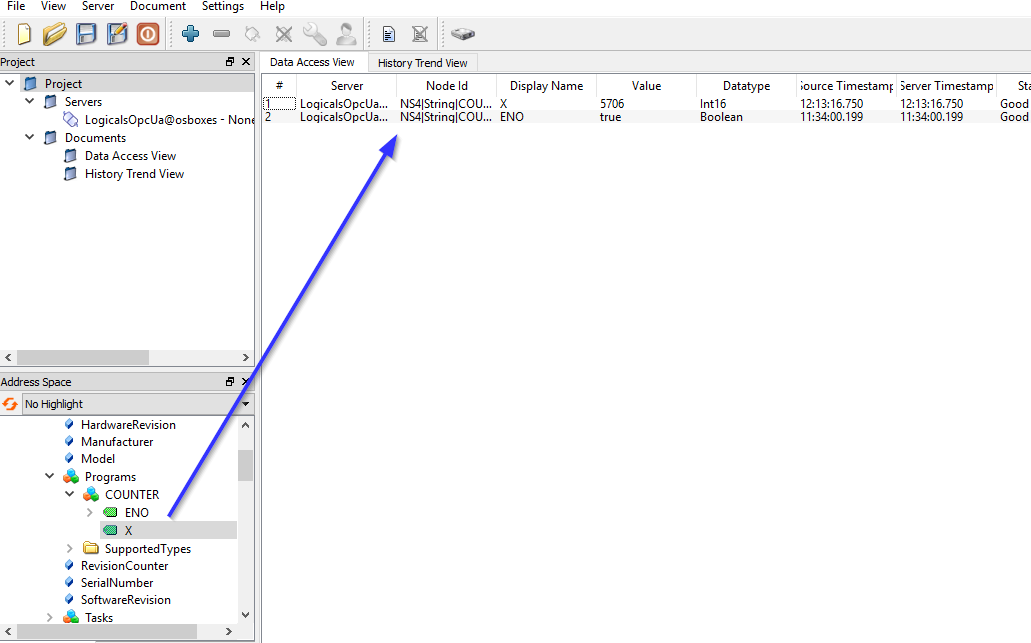
![]() The OPC UA client displays the variables with the following data types as follows:
The OPC UA client displays the variables with the following data types as follows:
|
Dat type of variable |
Display within the OPC UA client |
|
DATE_AND_TIME |
DateTime |
|
DATE |
DateTime with timestamp 00:00:00 |
|
TIME |
INT64 in nano seconds |
|
TIME_OF_DAY |
INT64 in nano seconds |