OLT-fields in FBD
An OLT-field (OLT for "online test") is intended to display the current value of the attached element (or of a sub-element) on the →PLC and to be able to change this value, if the connection to the PLC has been established and an →instance context has been set for the FBD-object. The attachment is automatically created when the OLT-field is created.
An OLT-field for a FORCEMRK block can be used to change the value of an →assignment so that logi.CAD 3 uses a specified force value instead of the actual value for the assignment. It is possible to toggle back to the actual value for the assignment at any time.
The following principles are valid:
Within the FBD-editor for →programs or →function blocks, an OLT-field can be created for elements that have a value during the execution on the →PLC.
Within the FBD-editor for →functions, an OLT-field cannot be created at all.
If the creation of OLT-fields is possible within the FBD-editor, it is possible (![]() ) or not (
) or not (![]() ) to create an OLT-field for the following elements:
) to create an OLT-field for the following elements:
|
Element |
An OLT-field can be created. |
|
a →value field containing a declared →variable |
|
|
another value field (e.g. with a constant literal) |
Restriction: At present, no values are displayed within such OLT-fields. |
|
an input or output of a →function block instance |
|
|
a function block instance itself |
|
|
a
FORCEMRK block |
|
|
Restriction: These OLT-fields display a value in case of the logi.CAD 3 default scope. |
|
|
|
|
|
a function itself |
|
|
an SFC-element In particular, for the following part of the SFC-element:
|
Restriction: At present, no values are displayed within the OLT-fields for SFC-elements. |
|
|
Representation
![]() Depending on the configuration of your logi.CAD 3 version, the FBD-editor and its elements might be displayed differently in your logi.CAD 3 version than illustrated in the IDE documentation. This is the case, if logi.cals or the system integrator has changed the styles for the FBD-editor. Subsequently, the illustration in the IDE documentation are symbolic images and the representation in your logi.CAD 3 version takes precedence for the valid representation. In case of doubts, please contact logi.cals or your system integrator.
Depending on the configuration of your logi.CAD 3 version, the FBD-editor and its elements might be displayed differently in your logi.CAD 3 version than illustrated in the IDE documentation. This is the case, if logi.cals or the system integrator has changed the styles for the FBD-editor. Subsequently, the illustration in the IDE documentation are symbolic images and the representation in your logi.CAD 3 version takes precedence for the valid representation. In case of doubts, please contact logi.cals or your system integrator.
logi.cals recommends that you and/or your system integrator do not use yellow shades when designing FBD-elements because the color "Yellow" is used for tracking safe signals when developing safety-related applications. logi.CAD 3 does not check if colors are already used elsewhere. So the use of the yellow shades by you and/or your system integrator could have the consequence that "yellow" might also identify a non-safe logic as well.
Normal OLT-fields
Normal OLT-fields are the OLT-fields that are not created for a FORCEMRK block.
Example for OLT-fields that are associated with value fields containing a variable:
|
No displayed value |
With displayed value |
|
|
|
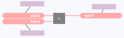
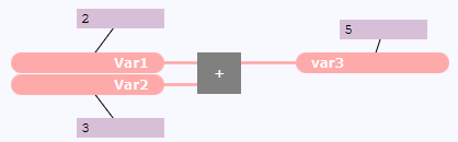
The assignment of the OLT-field is represented by a direct line.
Example for OLT-fields that are displaying a sub-element of the variable:
|
No displayed value |
With displayed value |
|
|
|
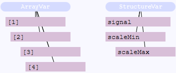
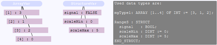
The sub-element is being defined when editing the OLT-field.
OLT-fields for a force marker
OLT-fields for a force marker are created for a FORCEMRK block . The OLT-fields for a force marker differ from the normal OLT-fields.
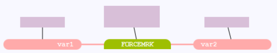
Example for an OLT-field that is associated with a FORCEMRK block – in contrast to the OLT-fields that are associated to value fields:
|
No displayed value |
With displayed value |
|
|
Here the value 5 is assigned to var2 . This value is the actual value that is assigned by var1 .
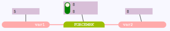
Here the specified force value 8 is assigned to var2 although var1 would still assign the value 5.
Use the force switch within the OLT-field (the slider within the OLT-field) to toggle between the actual value and a force value. Details: See "Creating or editing OLT-fields in FBD". |
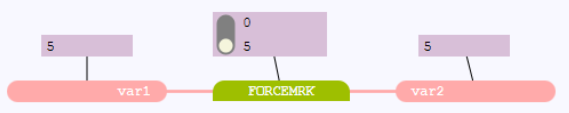
An OLT-field for a force marker consists of 3 parts:
The force switch is a slider on the left side. The force switch indicates whether the actual value (displayed as
 ) or the force value (displayed as
  ) is written to the PLC. Click onto the force switch in order to toggle between the actual value and the force value. The value displayed in the lower part is automatically updated.
The upper part displays the force value (e.g. the value 8). The force value is a value that you can specify. Double-click the upper part and enter the force value in the dialog
The lower part displays the value that is written to the PLC. In the case of the force switch
, the actual value is displayed (referring to the example, 5 is displayed). In case of the force switch
, the force value is displayed (referring to the example, 8 is displayed).
Restrictions
The restrictions are valid for normal OLT-fields as well as for OLT-fields for a force marker.
Restriction for the representation
If the OLT-field displays a value for STRING variables with a defined length, the displayed characters depend on the following assignment. Example: If a STRING variable with 100 characters is assigned to a STRING variable with 20 characters, the OLT-field just displays the 20 assigned characters.
If the OLT-field displays a value for STRING variables with an undefined length, the OLT-field displays just up to 256 characters.
Actions for OLT-fields
Page:Moving FBD-elements