Order of statements within an FBD-network
After the network to be evaluated has been determined, logi.CAD 3 determines the order of the statements to be →evaluated within the network.
Rules for the order
First logi.CAD 3 checks which statements within the network that can be evaluated according to the →IEC-standard.
A statement can be evaluated, if all other statements creating input values for this statement can be evaluated in the current cycle.Quoting the IEC-standardNo element of a network shall be evaluated until the states of all of its inputs have been evaluated.
The evaluation of a network element shall not be complete until the states of all of its outputs have been evaluated.
The evaluation of a network is not complete until the outputs of all of its elements have been evaluated, even if the network contains one of the execution control elements.
Implementer-specific realization
The IEC-standard defines that i t shall be possible for the user to utilize an implementer-specific means to determine the order of execution of the elements in an explicit →feedback loop, for instance by selection of a feedback variable.
Therefore, logi.CAD 3 attempts to resolve a feedback loop using feedback variables. But if there is no variable in the feedback loop, the calls are used to resolve the feedback loop.
Subsequently, logi.cals recommends that you use such feedback variables in feedback loops. On the one hand, you can better control the execution order of the network elements by using a feedback variable. And on the other hand, you remain compliant with the IEC-standard, since feedback loops without a feedback variable are not considered in the IEC-standard.
Mind the following: If a variable is used as array index itself or within the array index, logi.CAD 3 considers this variable as an input as well.
If logi.CAD 3 determines that
only one of the statements within the network can be evaluated, this statement is evaluated.
several statements within the network can be evaluated, logi.CAD 3 prioritizes these statements for evaluation according to this order:
Assignments rank above calls.
Assignment statements (short: →assignments): Assignments are created by positioning a value field and by connecting it with a call or another value field.
Here you see assignments to the variable var3 and var5 respectively:
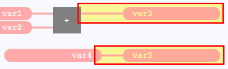
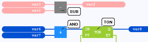
Call statements (short: →calls): Calls are created by positioning a →function block or a →function.
Here you see calls of the SUB function, AND function and TON function block respectively:
 In principle, SFC elements of an →SFC network behave like calls within the network. But observe that SFC elements are evaluated according to predefined rules of evolution
If several assignments can be evaluated, logi.CAD 3 checks whether assignments follow immediately after a call. Such assignments are evaluated prior to other ones because these assignments are influenced by the connected input EN of the call (see also the subsequent rule on a call with connected input EN).
If there are still several assignments to be evaluated, logi.CAD 3 determines the graphical position of these assignments: The assignment most top/left is evaluated (top is applied before left). Mind the following: For assignments, the crucial factor is the position of the input of the value field to which the assignment is done. – see examples below
If not one of the assignments but several calls can be evaluated, logi.CAD 3 determines the graphical position of these calls: The call most top/left is evaluated (top is applied before left). Mind the following: For calls, the crucial factor is the upper left corner of the call (without a possibly displayed instance name). – see examples below
not one of the statements within the network can be evaluated, there is a →feedback loop. In this case logi.CAD 3prioritizes these statements to the following order in order to resolve the feedback loop:
First logi.CAD 3 tries to reduce the sum of the statements to be evaluated: logi.CAD 3 will ignore all statements which follow the feedback loop and do not contain any other feedback loop.
Regarding the remaining statements, logi.CAD 3 tries to determines a feedback variable. In order to do so, logi.CAD 3 selects the variable with the assignment being most bottom/right. This is valid as well: For assignments, the crucial factor is the position of the input of the value field to which the assignment is done.
logi.CAD 3considers this variable as evaluated until it can actually be evaluated.If there are no assignments in the feedback loop, logi.CAD 3 selects the call of the function block being most top/left. This is valid as well: For calls, the crucial factor is the upper left corner of the call (without a possibly displayed instance name).
logi.CAD 3considers the outputs of this call as evaluated until the call can actually be evaluated. Immediately following assignments are put on hold concerning the evaluation until the call has actually been evaluated . This just leaves the following calls to be evaluated.
there is a call with a connected input EN, the depending assignment is only executed, if the input EN=TRUE. See "Example for behavior with connected EN".
As soon as logi.CAD 3 has evaluated a statement or resolved a feedback loop, the rules are applied to determine the next statement to be evaluated (starting with the 1. step).
The rules are applied until all statements of the network are evaluated. Then logi.CAD 3 determines the next network to be evaluated.
![]() logi.CAD 3 displays an execution order for each call. In contrast to this, the execution order for a value field is only displayed, if a calculation must be done for it. Hence, the execution order is not displayed for the following value fields:
logi.CAD 3 displays an execution order for each call. In contrast to this, the execution order for a value field is only displayed, if a calculation must be done for it. Hence, the execution order is not displayed for the following value fields:
value field with a →constant
value field with a →variable , if the input of the value field is not connected
The following "examples for order, without feedback loop" will explain this display and non-display respectively.
![]() The rules in this article and the following examples apply to the default configuration of
logi.CAD 3
.
Different rules are applied, if you have used the start option lc3.fbdStatementSortLC32 to activate the execution order modeled after the predecessor product logi.CAD/32. The behavior modeled on the predecessor product corresponds to the behavior in the predecessor product with the logi.CAD/32 environment variable LC32_SORTORDER_TAR_DEP_CHECK=1. Details about the rules of the execution order for logi.CAD/32 can be found in the online help of logi.CAD/32. the information about LC32_SORTORDER_TAR_DEP_CHECK=1 can be found in the documentation for administrators of the predecessor product (in the article "Defining Processing Variant Concerning Variables Used as Array Index").
The rules in this article and the following examples apply to the default configuration of
logi.CAD 3
.
Different rules are applied, if you have used the start option lc3.fbdStatementSortLC32 to activate the execution order modeled after the predecessor product logi.CAD/32. The behavior modeled on the predecessor product corresponds to the behavior in the predecessor product with the logi.CAD/32 environment variable LC32_SORTORDER_TAR_DEP_CHECK=1. Details about the rules of the execution order for logi.CAD/32 can be found in the online help of logi.CAD/32. the information about LC32_SORTORDER_TAR_DEP_CHECK=1 can be found in the documentation for administrators of the predecessor product (in the article "Defining Processing Variant Concerning Variables Used as Array Index").
The differences betwwen
logi.CAD/32
and
logi.CAD 3
in the default configuration are specified in the description "Differences: Predecessor product to current product
", search for the lines with the text "feedback loops" and "execution order" in this description.
Examples for order, without feedback loop
The order of the statements is displayed by the execution order (= number displayed within the red rectangle) within the examples.
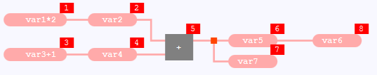
Example 1: Assignments that can be evaluated at the same time
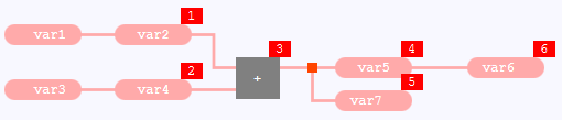
The execution order is not displayed for the value field with var1 and the one with var3 . Reason: There is no calculation needed for these value fields.
The statements are evaluated in this order:
assignment to var2 – Reason: The assignment to var2 is evaluated due to its graphical position. The assignment to var4 can be evaluated at the same time but the one to var2 is most top.
assignment to var4 – Reason: Only this assignment can be evaluated.
call of the ADD blocks – Reason: Only this call can be evaluated.
assignment to var5 – Reason: The assignment to var5 is evaluated due to its graphical position. The assignment to var7 can be evaluated at the same time (it also follows immediately after the call of the ADD block) but the one to var5 is more top.
assignment to var7 – Reason: The assignment to var7 follows immediately after the call of the ADD block and hence it is evaluated prior to the assignment to var6 (even though the assignment to var6 is more top).
assignment to var6 – Reason: Only this assignment can be evaluated.
Example 2: Assignments that can be evaluated at the same time, seemingly changed position
As for example 1, the execution order is not displayed for the value field with var1 and the one with var3 and the statements are evaluated in the same order.
The assignments to var2 and var4 are evaluated in the same order because they are positioned as in example 1.
The assignments to var5, var7 and var6 are evaluated in the same order because the assignments to var5 and var7 still follow immediately after the call of the ADD block. Hence, they are evaluated prior to the assignment to var6 (even though the assignment to var6 is most top out of those 3 assignments).
Example 3: Like example 1 but with calculations for the left value fields
In contrast to example 1, an execution order is displayed for the left value fields because a calculation needed for them .
Now the statements are evaluated in this order:
calculation for var1*2 – Reason: The value field with var1*2 is evaluated due to its graphical position. The calculation for var3+1 can be evaluated at the same time but the one for var1*2 is most top.
assignment to var2 – Reason: The assignment to var2 is evaluated due to its graphical position. The calculation for var3+1 can be evaluated at the same time but the assignment to var2 is most top.
calculation for var3+1 – Reason: Only this calculation can be evaluated.
remaining evaluation: see example 1, from assignment to var4 onwards
Example 4: Calls that can be evaluated at the same time
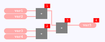
The execution order is not displayed for the value field with var1 , the one with var2, the one with var3 and the one with var4 . Reason: There is no calculation needed for these value fields.
The statements are evaluated in this order:
the top, left call of the ADD block – Reason: The top, left call of the ADD block is evaluated due to its graphical position. The bottom, left ADD block can be evaluated at the same time but the other call is most top.
the bottom, left call of the ADD block – Reason: Only this call can be evaluated.
the right call of the ADD block – Reason: Only this call can be evaluated.
assignment to var5 – Reason: Only this assignment can be evaluated.
Example 5: Assignments and calls that can be evaluated
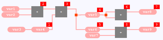
The execution order is not displayed for the value field with var1 , the one with var2, the one with var3 and the one with var7 . Reason: There is no calculation needed for these value fields.
The statements are evaluated in this order:
assignment to var4 – Reason: Assignments rank above calls. The assignment can be evaluated at the same time as the left call of the ADD block can be evaluated.
the left call of the ADD block – Reason: Only this call can be evaluated.
the middle call of the ADD block – Reason: Only this call can be evaluated.
assignment to var5 – Reason: The assignment to var5 is evaluated due to its graphical position. The assignment to var6 can be evaluated at the same time (it also follows immediately after the call of the ADD block) but the one to var5 is most top.
assignment to var6 – Reason: Assignments rank above calls. The assignment can be evaluated at the same time as the top, right call of the ADD block can be evaluated.
the top, right call of the ADD block – Reason: The top, right call of the ADD block is evaluated due to its graphical position. The bottom, right ADD block can be evaluated at the same time but the other call is most top.
assignment to var8 – Reason: Assignments rank above calls. The assignment can be evaluated at the same time as the bottom, right call of the ADD block can be evaluated.
the bottom, right call of the ADD block – Reason: Only this call can be evaluated.
assignment to var9 – Reason: Only this assignment can be evaluated.
Example 6: Like example 5 but with calls within value fields
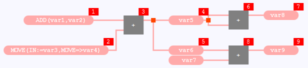
In contrast to example 5, an execution order is displayed for the most left value fields because a calculation needed for them .
Now the statements are evaluated in this order:
calculation for ADD(var1,var2) – Reason: The value field with ADD(var1,var2) is evaluated due to its graphical position. The calculation for MOVE(IN:=var3,MOVE=>var4) can be evaluated at the same time but the one for ADD(var1,var2) is most top.
calculation for MOVE(IN:=var3,MOVE=>var4) – Reason: Only this calculation can be evaluated.
the left call of the ADD block – Reason: Only this call can be evaluated.
remaining evaluation: see example 5, from assignment to var5 onwards
Example 7: Statements with a variable as array index
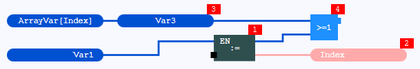
The execution order is not displayed for the value field with ArrayVar[Index] and the one with var1 . Reason: There is no calculation needed for these value fields.
The statements are evaluated in this order:
the call of the MOVE block – Reason: Only this call can be evaluated.
Note: The assignment to Var3 cannot be evaluated because the variable Index is used as array variable. This variable must be evaluated so that the assignment to Var3 can be evaluated.assignment to Index – Reason: Only this assignment can be evaluated.
assignment to Var3 – Reason: Only this assignment can be evaluated.
Note: Now the assignment to Var3 can be evaluated because the variable Index has already been evaluated.the call of the OR block – Reason: Only this call can be evaluated.
Examples for order, with feedback loops
Example 1: Explicit feedback loop with assignments
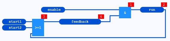
As not one of the statements within the network can be evaluated, there is a feedback loop. This is an explicit feedback loop. As no statements follow the feedback loop, the sum of the statements is not reduced when resolving the feedback loop. feedback is determined as feedback variable because the value field with feedback is lower than the value field with run. Subsequently, feedback is considered as evaluated and the statements are evaluated in this order:
call of the AND block – Reason: Only this call can be evaluated.
assignment to run – Reason: Only this assignment can be evaluated.
call of the OR block – Reason: Only this call can be evaluated.
assignment to feedback – Reason: Only this assignment can be evaluated.
In contrast here a similar network but without the feedback loop:
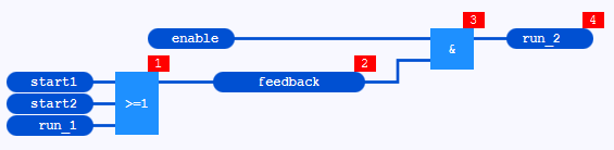
These statements are evaluated in this order:
call of the OR block – Reason: Only this call can be evaluated. In contrast to the network with the explicit feedback loop, all inputs for OR can be evaluated.
assignment to feedback – Reason: Only this assignment can be evaluated.
call of the AND block – Reason: Only this call can be evaluated.
assignment to run_2 – Reason: Only this assignment can be evaluated.
Example 2: Implicit feedback loop with assignments
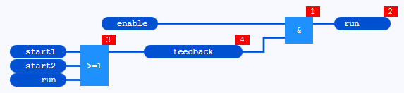
Similar to example 1, but this is an implicit feedback loop. There are no differences to example 1, when reducing the statements, determining the feedback variable and evaluating the statements.
Example 3: Explicit feedback loop only with function blocks, without assignment
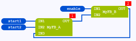
As not one of the statements within the network can be evaluated, there is a feedback loop. This is an explicit feedback loop. As no statements follow the feedback loop, the sum of the statements is not reduced when resolving the feedback loop. Moreover, it is not possible to determine a feedback variable because there is no assignment. Subsequently, the MyFB_B block is determined to resolve the feedback loop because it is most top. Now logi.CAD 3 considers the output of this call as evaluated. Hence, the statements are evaluated in this order:
call of the MyFB_A block – Reason: Only this call can be evaluated.
call of the MyFB_B block – Reason: Only this call can be evaluated.
Example 4: Explicit feedback loop only with functions, without assignment
Example 3 but with functions (instead of function blocks) is highlighted as faulty because such feedback loops are not supported in logi.CAD 3.
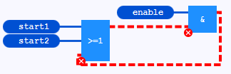
![]() Depending on your configuration of logi.CAD 3, example 4 might be highlighted as a warning (instead of an error). See under "→Feedback loop" for details.
Such a changed configuration of
logi.CAD 3
displays an order of statements for a feedback loop that contains only functions
:
Depending on your configuration of logi.CAD 3, example 4 might be highlighted as a warning (instead of an error). See under "→Feedback loop" for details.
Such a changed configuration of
logi.CAD 3
displays an order of statements for a feedback loop that contains only functions
:
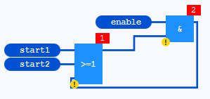
Now what is the order for the evaluation of the statements, if the feedback loop contains only functions and this feedback loop is highlighted as a warning?
logi.CAD 3 uses the rules to resolve the feedback loop as they are described under "Rules for the order" – but instead of using the call of a function block to resolve the feedback loop, logi.CAD 3 is using the call of a function. This call of the function is determined as this:
logi.CAD 3 selects the call of the function being most top/left. This is valid as well:
For calls, the crucial factor is the upper left corner of the call. logi.CAD 3
considers the outputs of this call as evaluated until the call can actually be evaluated. Immediately following assignments are put on hold concerning the evaluation until the call has actually been evaluated.
Regarding the above example, the call of the AND block is determined because it is more top. Hence, logi.CAD 3 considers the output of this call as evaluated and the statements are evaluated in this order:
call of the OR block – Reason: Only this call can be evaluated.
call of the AND block – Reason: Only this call can be evaluated.
As soon as you insert an assignment or a function block into the feedback loop, logi.CAD 3 uses again the rules to resolve the feedback loop as they are described under "Rules for the order" .
Example 5: Feedback loop with following statements
Each of the next examples is showing a feedback loop occurring for the call of the FB_D block. As all other statements depend on FB_D, not one of the statements can be evaluated at first.
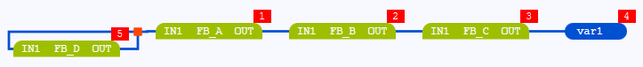
First the sum of the statements is reduced when resolving the feedback loop. Reason: There are statements following the feedback loop and these statements do not contain any other feedback loop. This leaves the call of the FB_D block as the only statement for the following selection of the call of the function block being most top/left (a feedback variable cannot be determined because the assignment to var1 is one of the ignored statements). Subsequently, the output of FB_D is considered as evaluated and the statements are evaluated in this order:
call of the FB_A block – Reason: The call of the FB_A block and the call of the FB_D block can be evaluated at the same time. FB_A is evaluated due to its graphical position (FB_A is more top that FB_D).
call of the FB_B block – Reason: The call of the FB_B block and the call of the FB_D block can be evaluated at the same time. FB_B is evaluated due to its graphical position (FB_B is more top that FB_D).
call of the FB_C block – Reason: The call of the FB_C block and the call of the FB_D block can be evaluated at the same time. FB_C is evaluated due to its graphical position (FB_C is more top that FB_D).
assignment to var1 – Reason: The assignment to var1 and the call of the FB_D block can be evaluated at the same time. As the assignment to var1 does not immediately follow the call of the FB_D block, it is not put on hold concerning the evaluation. Hence, the following is valid: Assignments rank above calls. Thus, the assignment to var1 is evaluated.
call of the FB_D block – Reason: Only this call can be evaluated.
The following example is showing a 2nd feedback loop (for the call of the FB_C2 block). This results in a different order.
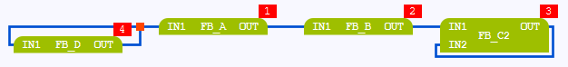
Here the sum of the statements cannot be reduced in order to resolve the feedback loops. Reason: There are statements following the 1st feedback loop but these statements contain the other feedback loop. This leaves all calls to resolve the feedback loops. At first, logi.CAD 3 determines the feedback loop to be resolved. This determination is done using the calls FB_D (contained in the left feedback loop) and FB_C2 (contained in the right feedback loop). Since FB_C2 is located more top than FB_D, the right feedback loop containing FB_D is resolved first. Hence, the output of FB_C2 is considered as evaluated until this call can actually be evaluated. As a result, the right feedback loop does not exist for the further evaluation. However, since none of the statements can be evaluated, the left feedback loop containing FB_D on the left is resolved. Hence, the output of FB_D is also considered to be evaluated, whereby the call of the FB_A block can now be evaluated. Subsequently, the statements are evaluated in this order:
call of the FB_A block – Reason: Only this call can be evaluated.
call of the FB_B block – Reason: Only this call can be evaluated.
call of the FB_C2 block – Reason: After the evaluation of FB_B, FB_C2 can actually be evaluated.
call of the FB_D block– Reason: Only this call can be evaluated.
The following example shows a construct where assignments and a call are immediately following a call within a feedback loop:
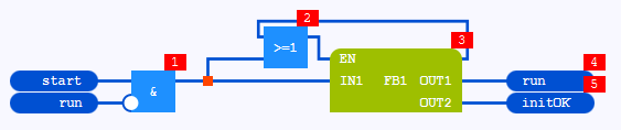
As not one of the statements can be evaluated, there is a feedback loop. Here, the statements following the first feedback loop (due to run) contain a second feedback loop (the one from the call of OR block to the call of the FB1 block). So the sum of the statements is not reduced. This leaves all statements to resolve the feedback loop. First, initOK is determined as feedback variable because the value field with initOK is more bottom than the value field with run. However, none of the statements can be evaluated. So the next feedback variable is determined – this is run. Hence, the statements are evaluated in this order:
call of the AND block – Reason: Only this call can be evaluated.
After AND has been evaluated, not one of the next statements can be evaluated (this is the next feedback loop). In order to resolve this feedback loop, the sum of the statements is reduced at first. Reason: The assignments after the call of the FB1 block follow the feedback loop and do not contain any other feedback loop. This leaves the call of the OR block and the call of the FB1 block for the determination of the call of the function block being most top/left (a feedback variable cannot be determined because the assignments are part of the ignored statements). Here, the call of the FB1 block is determined to resolve the feedback loop because the OR block is a function. Subsequently, the outputs of FB1 are considered as evaluated and it is possible to evaluate the remaining statements. As the assignment to run and initOK are directly following the call of FB1, these assignments are put on old concerning the evaluation until the call of FB1 has actually been evaluated .call of the OR block – Reason: After the 2nd feedback loop has been evaluated, only this call can be evaluated because all of its input values can be evaluated.
call of the FB1 block – Reason: Only this call can be evaluated.
assignment to run – Reason: After the actual evaluation of FB1, the assignments to run and initOK can be evaluated at the same time. As the value field with run is more top, the assignment to run is evaluated first.
assignment to initOK – Reason: Only this assignment can be evaluated.
Example 6: Feedback loop – changed position of statements
Each of the next examples is showing a feedback loop. Mind that a different feedback variable or a different call of a function block is determined in the example – if the position of the crucial element has changed.
|
The example is showing a feedback loop from the value field with var2 to the call of the AND block. The assignment to var3 cannot be evaluated (because it follows the call of the AND block) and it will be ignored to resolve the feedback loop.
|
|
The position of the value fields with var1 and var2 has been changed for this example. This results in a different order whereas the call of a different block does not result in a different order.
|
|
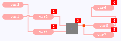
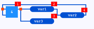
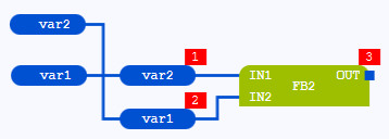
This example shows a more complex construct. Statements do not follow the feedback loop in this example. Hence, the sum of the statements is not reduced to resolve the feedback loop. var1 is determined as feedback variable and is considered as evaluated because the right value field with var1 is more right than the value field with var2. Subsequently, the statements are evaluated in this order:
|
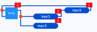
|
The position of the value field with var2 has been changed for this example. This results in a different order var2 is determined as feedback variable and is considered as evaluated because the value field with var2 is lower than the value field with var1. Afterwards there are still not any statements that can be evaluated. Therefore, a new feedback variable is determined, this is var1. Mind that var1 as well as var2 are considered as evaluated. Subsequently, the statements are evaluated in this order:
|
|
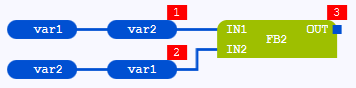
Compare the left with the right network. The statements in the left network are evaluated in the same order as the ones in the right network. Reason: The position of the assignments to var2 and var1 has not changed. |
|
|
|
|
|
var1 is determined as feedback variable for both networks and is considered as evaluated because the right value field with var1 is lower than the right value field with var2. Subsequently, the statements are evaluated in this order:
|
|
|
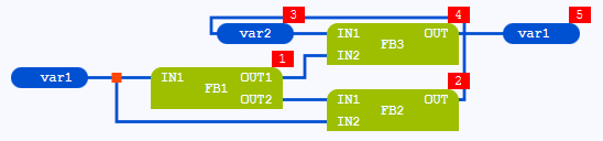
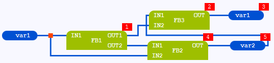
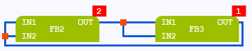
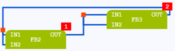
Compare the left with the right network. The statements in the left network are evaluated in a different order as the ones in the right network. Reason: The position of the calls has changed. |
|
|
|
|
|
A feedback variable cannot be determined in both networks because there are no assignments. Subsequently, the call of the block most top/left is determined to resolve the feedback loop. This is a different call. |
|
|
In the left network, the call of the FB2 block is determined. Now logi.CAD 3 considers the output of this call as evaluated. Hence, the statements are evaluated in this order:
|
In the right network, the call of the FB3 block is determined. Now logi.CAD 3 considers the output of this call as evaluated. Hence, the statements are evaluated in this order:
|
Example 7: A practical example for a feedback loop
The following example shows a feedback loop from var1 to var1.
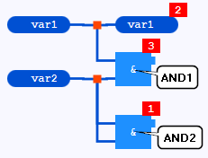
The statements are evaluated in this order:
the bottom call of the AND block (identified as AND2) – Reason: Only this call can be evaluated. (All of its input values can be evaluated.)
assignment to var1 – Reason: After AND2 has been evaluated, not one of the statements can be evaluated. The assignment to var1 is a feedback loop and the top call of the AND block receives its input value from var1. In order to resolve the feedback loop, the sum of the statements cannot be reduced as there are no statements following the feedback loop. Hence, var1 is determined as feedback variable and is considered as evaluated. Afterwards the assignment as well as the top call of the AND blocks can be evaluated. As assignments rank above calls, the assignment to var1 is evaluated.
the top call of the AND block (identified as AND1) – Reason: Only this call can be evaluated.
Example 8: Nested feedback loops
The following examples shows that not one of the statements can be evaluated at first.
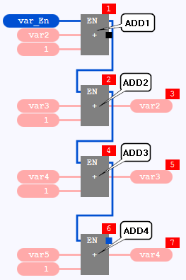
This example contains several feedback loops: from ADD1 to ADD2, from ADD2 to ADD3 and from ADD3 to ADD4 – ADD2 as well as ADD3 are involved in 2 feedback loops, i.e., there are nested feedback loops. In detail:
The top call of the ADD block (identified as ADD1) must not be evaluated because one of its input is connected to var2 and var2 is calculated by the following call of the ADD block (identified as ADD2).
ADD2 must not be evaluated either. Its input EN receives the result from the output ENO of ADD1. Moreover, the 2nd input is connected to var3 and var3 is calculated by the following call of the ADD block (identified as ADD3).
Similar to ADD2, ADD3 must not be evaluated either. Its input EN receives the result from the output ENO of ADD2. Moreover, the 2nd input is connected to var4 and var4 is calculated by the following call of the ADD block (identified as ADD4).
ADD4 must not be evaluated either. Its input EN receives the result from the output ENO of ADD3.
The statements are evaluated in this order:
the top call of the ADD block (identified as ADD1) – Reason: In order to resolve the feedback loop, the sum of the statements cannot be reduced: There are statements following the 1st feedback loop but there are feedback loops in them. Hence, var4 is determined as feedback variable (its value field is most bottom/right), it is considered as evaluated. But there is still not one statement that can be evaluated. Therefore, a new feedback variable is determined from among the remaining statements, this new feedback variable is var3 (its value field is most bottom/right), it is considered as evaluated. But there is still not one statement that can be evaluated. Again, a new feedback variable is determined from among the remaining statements, this new feedback variable is var2 (its value field is most bottom/right), it is considered as evaluated. Now the top call of the ADD block (identified as ADD1) in the only statement that can be evaluated because all of its input values can be evaluated.
the next call of the ADD block (identified as ADD2) – Reason: Only this call can be evaluated. All of its input values can be evaluated because var3 is still considered as evaluated because it has been determined as feedback loop.
assignment to var2 – Reason: As the assignment and ADD3 can be evaluated at the same time (var4 is still considered as evaluated because it has been determined as feedback loop), the assignment is evaluated (assignments rank above calls).
the next call of the ADD block (identified as ADD3) – Reason: Only this call can be evaluated. All of its input values can be evaluated because var4 is still considered as evaluated – as mentioned above.
assignment to var3 – Reason: Assignments rank above calls. The assignment can be evaluated at the same time as the bottom, right call of the ADD block can be evaluated.
the bottom call of the AND block (identified as AND4) – Reason: Only this call can be evaluated.
assignment to var4 – Reason: Only this assignment can be evaluated.
Example 9: Complex example with several feedback loops
The following example contains 2 feedback loop that are identifiable immediately:
one between the FB2 block and the FB3 block and
one between the RS blocks
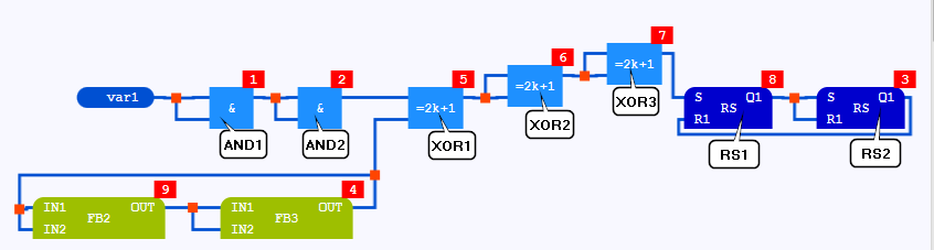
The statements are evaluated in this order:
the left call of the AND block (identified as AND1) – Reason: Only this call can be evaluated. (All of its input values can be evaluated.)
the next call of the AND block (identified as AND2) – Reason: Only this call can be evaluated.
the right call of the RS block (identified as RS2) – Reason: In order to resolve the feedback loop, the sum of the statements cannot be reduced: There are statements following the 1st feedback loop but there is a feedback loop in them. Hence, the call of a function block being most top/left is determined (a feedback variable cannot be determined as there is no assignment in the network). The call of a function block being most top/left (observe that the XOR blocks are functions) i s the left call of the RS block (identified as RS1). The output of RS1 is considered as evaluated. Subsequently, only the right call of the RS block (identified as RS2) can be evaluated because all of its input values can be evaluated.
call of the FB3 block – Reason: There is not one statement that can be evaluated after the evaluation of RS2. In order to resolve the feedback loops, the call of a function block being most top/left is determined again. Now this is the call of the FB2 block. The output of FB2 is considered as evaluated. Subsequently, only the right call of the RS block (identified as RS2) can be evaluated because all of its input values can be evaluated. Subsequently, only the call of the FB3 block can be evaluated because all of its input values can be evaluated.
the left call of the XOR block (identified as XOR1) – Reason: The call of the FB2 block and the left call of the XOR block (identified as XOR1) can be evaluated at the same time. XOR1 is evaluated due to its graphical position (XOR1 is more top that FB2).
the middle call of the XOR block (identified as XOR2) – Reason: The call of the FB2 block and the middle call of the XOR block (identified as XOR2) can be evaluated at the same time. XOR2 is evaluated due to its graphical position (XOR2 is more top that FB2).
the right call of the XOR block (identified as XOR3) – Reason: The call of the FB2 block and the right call of the XOR block (identified as XOR3) can be evaluated at the same time. XOR3 is evaluated due to its graphical position (XOR3 is more top that FB2).
the left call of the RS block (identified as RS1) – Reason: The call of the FB2 block and the left call of the RS block (identified as RS1) can be evaluated at the same time. RS1 is evaluated due to its graphical position (RS1 is more top that FB2).
call of the FB2 block – Reason: Only this call can be evaluated.
Example for behavior with connected EN
It is possible that the execution within the network is influenced by a call with a connected input EN. Reason: A so-called EN-bracketing will include the immediately following assignment that depends on this call. All following statements are positioned outside this EN-bracketing.
The state of the input EN determines whether the depending assignment is executed or not. In case of EN=TRUE, it is executed. In case of EN=FALSE, it is not executed.
Example: The statements contain the call of a MOVE block with connected EN.

The assignment to Var2 is positioned in the EN-bracketing. Hence, they depend on the state of the input EN.
The statements are evaluated in this order:
the call of the MOVE block – Reason: Only this call can be evaluated. (The assignment to Var3 cannot be evaluated because the MOVE block assigns a value to Var2.)
assignment to Var2 – Reason: Only this assignment can be evaluated.
This assignment is positioned into the EN-bracketing because it depends on MOVE. All other statements are positioned outside the EN-bracketing.assignment to Var3 – Reason: Only this assignment can be evaluated.
the call of the OR block – Reason: Only this call can be evaluated.
The following code is created (simplified representation):
IF (Var1 != false) { MOVE(false); Var2:=MOVE.OUT1; }Var3:=Var2;OR(IN1:=Var3,IN2:=MOVE.ENO);This simplified code illustrates that the assignment to Var2 is executed only in case of Var1=TRUE. Reason: In case of Var1=TRUE, EN=TRUE is valid as well.