Importing a Simulink model into a project
logi.CAD 3 enables you to import an existing →Simulink model into a →project of logi.CAD 3. The import is not provided in all variants of logi.CAD 3.
Content of this article:
Exporting the Simulink model as logi.CAD 3 MATLAB export bundle
Importing the logi.CAD 3 MATLAB export bundle into logi.CAD 3
Conditions for using the import
You have already installed the required license.
You have received the installation package com.logicals.simulink.export-x.y.z.zip from logi.cals. x.y.z is a placeholder for the respective version number.
 This installation package contains scripts that you have to execute in MATLAB.
You are using Version 2021a of MATLAB and Embedder Coder as a code generator (see https://de.mathworks.com/products/embedded-coder.html).
The import only supports time-discrete Simulink models. 2 or more different sampling times within a Simulink model are not supported for the import.
Moreover, observe the following: When the Simulink model depends on the cycle time, the Simulink user must decide on a way to handle this in the Simulink model. For instance, it is possible to define an explicit input in the Simulink model so that this input will be imported into logi.CAD 3. Subsequently, it is required to pass the time values to this input within the logi.CAD 3 application.The Simulink model corresponds to the requirements for a successful import.
In this Simulink model: Use POU-unique names (when possible, project- and POU-unique) for all C-identifiers that are available in a global namespace. See "The dos and don'ts when working, When creating blocks with C-code" for details.
You use the same logi.CAD 3 version for both partial steps of the import:
Exporting the Simulink model as logi.CAD 3 MATLAB export bundle
Unpack the installation package com.logicals.simulink.export-x.y.z.zip to a folder of your liking.
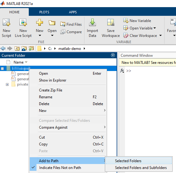
Add the path with the unpacked scripts to the search path of MATLAB.
Possibility 1: In MATLAB, go to the path with the unpacked scripts. Open the context menu for the folder and select the command Add to Path and Selected Folders.
Possibility 2: In the MATLAB Command Window, enter the following command (but replace path_to_folder_with_scripts by the path with the unpacked scripts): addpath('path_to_folder_with_scripts')
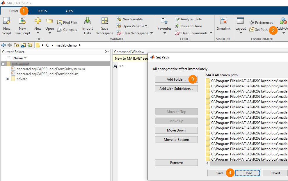
Possibility 3 so that the path is permanently added: In the ribbons of MATLAB on the tab HOME, select Set Path (provided in the group ENVIRONMENT) . Click Add Folder..., add the path with the unpacked scripts and click Save.
In MATLAB, open the Simulink model and the containing projects, if such projects exist.
Reason: The projects might contain so-called data dictionaries with user-defined types.In the MATLAB Command Window, execute one of the following scripts:
Script 1: Generate bundle based on a modelgenerateLogiCAD3BundleFromModel(modelName, outputFolder)
Replace the parameter modelName by the name of the opened model and outputFolder by the path in which the logi.CAD 3 MATLAB export bundle should be generated.
Example: generateLogiCAD3BundleFromModel('fuelsys_dd_controller', "C:\data\exported_bundles")Script 2: Generate bundle based on a model and subsystemgenerateLogiCAD3BundleFromSubsystem(modelName, subsystemQualifiedName, outputFolder)
Replace the parameters modelName and outputFolder as when using script 1. Moreover, replace subsystemQualifiedName by the qualified name of the subsystem.
Example: generateLogiCAD3BundleFromSubsystem('Overrun', 'Overrun/OvrRun', "C:\data\exported_bundles")Result of the script: A logi.CAD 3 MATLAB export bundle is generated based on the specified data. The name of this logi.CAD 3 MATLAB export bundle is: Simulink_Model_Name_logiCAD3Bundle.zip or Subsystem_Name _logiCAD3Bundle.zip – Example: OvrRun_logiCAD3Bundle.zip (OvrRun is the name of the subsystem.)
Possible warnings
Warnings will indicate when the Simulink model contains the following Simulink elements (see under "Requirements for the Simulink model" for details on them):
elements, if their name is a reserved keyword in ST
elements, if their name is not a valid →IEC-identifier
elements, if their names differ regarding case sensitivity
Subsequently, if you import the generated logi.CAD 3 MATLAB export bundle with such elements into a logi.CAD 3 project, these elements would be highlighted as faulty in logi.CAD 3. Therefore, the names of these elements are automatically corrected during the following import so that the corrected names do not cause an error in logi.CAD 3.
Importing the logi.CAD 3 MATLAB export bundle into logi.CAD 3
How to import the generated logi.CAD 3 MATLAB export bundle into the project of logi.CAD 3:
In menu File or from the context menu within the view containing the projects/resources, select Import...
In the wizard, expand the category Simulink Model Import, select Import Simulink Model and click Next >.
To locate a particular type: Enter a text (e.g. Simulink) into the field under Select an import wizard to show only the types that match the entered text.On the next wizard page, perform the following steps :
In the text box (left of Simulink bundle ), t ype in the full path and file name of the previously generated logi.CAD 3 MATLAB export bundle. Alternative: Click the button Browse to select the path and the file name on the file system.
In the list under Target project, select the project into which the logi.CAD 3 MATLAB export bundle should be imported.
This list contains all projects that are open in the view.Click Finish to start the import.
Result: The following objects are generated in the project. These objects are based on the logi.CAD 3 MATLAB export bundle:Object type
Meaning
The ST-object has the name of the Simulink model. It contains at least one →vendor block of the type "function block" with the same name. It is possible that this ST-object contains other ST language elements as well – the content depends on the exported Simulink model, e.g. a →structured data type.
Strings are imported with a default string length of 256. Do not edit these ST language elements! If you edit them anyway, the ST language elements will not match the imported Simulink model anymore.
It is possible to use the created function block in your logi.CAD 3 application as any other function block. For instance, it is possible to create a →function block instance and to call this function block instance, it is also possible to use the function block in a library.
Here are some references to additional documentation:
See "Declaration of function block instances in ST" and "Call of function block instance in ST" for the ST-syntax for function block instances and calling a function block instance.
See "Supported ST-syntax" for a list of all possible ST elements.
See the documentation "Administrator's Manual" for information about the pragmas of a vendor block, such as { CustomImplementation, CustomNamespace := Simulink }.
H- and C-files
The created vendor function block requires H- and C-files that contain the implementation of the vendor function block. These files are automatically created during the import into the project. By default, they are visible in the sub-folder src-code of the existing sub-folder src of the project.
Moreover, the H- and C-file from MATLAB are imported into the project . By default, these files are visible in the sub-folder src-code that has been created parallel to the existing sub-folder src of the project.
logi.CAD 3 provides the following possibilities so that these H- and C-files are not edited by mistake and they will continue to match the imported Simulink model :
Use the c onfiguration variable lc3.src_code.filter.enable to hide the sub-folder src-code with the C-/H-files. Details on the c onfiguration variables are listed in the documentation "Administrator's Manual".
By default, the H-/C-files for the imported Simulink model are write-protected. If the C-/H-files are displayed and you edit one of these files, a message indicates the write-protection. In this case, do not remove the write-protection so that the C-/H-files will still continue to match the imported Simulink model.
The library configuration already contains the vendor function block as library element – right after the statement IEC :=
Use this library configuration to create a library containing the vendor function block.
Here are some references to additional documentation:
See "Syntax for library configuration" for the syntax of the library configuration.
See "Creating and deploying a custom library" for steps on how to generated/deploy/install a library.
Possible warnings
Warnings will indicate when the import detects a conflict with an already existing element in the logi.CAD 3 project (see under "Requirements for the Simulink model"). Subsequently, the imported element is renamed to a unique name.
Possible error sources for the import
The messages Metamodel import failed (within the wizard and the error log) and Index 0 out of bounds for length 0 (only within the error log) indicates that it was not possible to successfully execute the import.
In this case, make sure at first whether you have used a
previously generated logi.CAD 3 MATLAB export bundle for the import. If you are able to exclude this error source, it is likely that the export of the Simulink model
as logi.CAD 3MATLAB export bundle has been faulty. Subsequently: Contact the manufacturer of the used library or block. Include your contact information, information on what you were doing in logi.CAD 3 and all messages listed in the Error Log view and/or Problems view. Moreover, include the
generated
logi.CAD 3 MATLAB export bundle, the Simulink model (incl. the possibly existing MATLAB projects) and the used MATLAB version.
Requirements for the Simulink model
Supported elements
The following Simulink elements are supported (= ![]() ) for a successful import:
) for a successful import:
primitive data types according to https://de.mathworks.com/help/simulink/ug/data-types-supported-by-simulink.html – with the exception of fixed-point data types
the following non-primitive data types:
one-dimensional arrays
multi-dimensional arrays (up to 4 dimensions)
enumerations
structures, like non-virtual S imulink.Bus
nested structures
virtual S imulink.Bus
Not-supported elements
The following Simulink elements are not supported (= ![]() ):
):
each fixed-point data type, e.g. half
code mapping customization, such as storage class, custom function name
If the Simulink model contains these not-supported elements , the logi.CAD 3 MATLAB export bundle cannot be generated. Corresponding messages are reported when the script is executed.
Automatically corrected elements
The following Simulink elements would either be highlighted as faulty in logi.CAD 3 or they would cause an error during the building of the application (= ![]() ):
):
elements, if their name is a reserved keyword in ST – Such elements are highlighted as faulty in logi.CAD 3.
Example: An element with the name of EN will be highlighted as faulty in logi.CAD 3 because the name EN is reserved for the input EN.elements, if their name is not a valid →IEC-identifier – Such elements are highlighted as faulty in logi.CAD 3.
Example: Simulink allows an element with the name LIM__SW5. In logi.CAD 3, this name is not allowed because the name must be a valid IEC-identifier.elements (e.g. variables), if their names differ regarding case sensitivity – Such elements might cause an error when the application is built in logi.CAD 3.
Example: Simulink allows 2 different variables Var1 and VAR1. In logi.CAD 3, Var1 and VAR1 are identified as the same element. This different interpretation of Var1 and VAR1 is likely to cause an error when building the application containing the function block with Var1 and VAR1.
So corresponding warnings are displayed during the export of a Simulink model with such Simulink elements (as logi.CAD 3 MATLAB export bundle). During the following import of the logi.CAD 3 MATLAB export bundle into logi.CAD 3, the names of these elements are automatically corrected so that the corrected names are not highlighted as faulty or do not cause an error when building the application.
The following Simulink elements are only reported when the logi.CAD 3 MATLAB export bundle is imported into logi.CAD 3 (= ![]() ):
):
data types, if an element with the same name already exists in the logi.CAD 3 project
function blocks, if an element with the same name already exists in the logi.CAD 3 project
During the import, these elements of the Simulink model are automatically renamed to a unique name because otherwise, elements with the same name would cause a conflict .