Connecting FBD-elements by lines
How to connect existing FBD-elements by a line in the →graphical FBD-editor:
|
1. |
Point to the corresponding part of an FBD-element so that the mouse pointer The mouse pointer is displayed for these parts: the left or right outer area of a→value field, the in-/output of a →call of a →block or the displayed name for the in-/output respectively, a →connector or a →continuation, the in-/output of a →step, of a →transition or of an →action block |
|
2. |
Press and hold the primary mouse button, then move the mouse pointer onto another FBD-element in the FBD-editor (see the following examples under 2.a. and 2.b.). These other FBD-elements are possible: a value field, a call or a particular input or output of the call, a connector or a continuation, a step, a transition, an action block or a particular input or output of these elements Observe:
|
|
3. |
Release the primary mouse button in order to connect both FBD-elements with the line. The FBD-editor creates orthogonal lines (see "Automatic routing of lines" for details). Special behavior for value fields:
|
Observe:
It is also possible to create several lines in one go (see the last of the following examples) .
If the created line is highlighted as faulty, this connection is causing an error. In this case, undo the created connection and connect the FBD-element with a different FBD-element.
The variables and/or the in-/outputs of the call must be of an identical data type or of one that can be converted implicitly.
A value field with the interface for a block automatically disappears, if the respective input has been connected to an FBD-element.
If you create a line across different pages, a direct line is automatically created.
If you release the primary mouse button over an empty space of the drawing field, an open line is automatically created. It is possible to dock such lines to other FBD-elements .
You are able to change the already created line so that it leads to a different FBD-element .
If the logic is ambiguously displayed due to the automatic line routing, best practice is to move the FBD-elements. See "The automatic line routing is ambiguously displaying the logic".
If you connect the input/output of a block for safe logic to a safe data type , the background color of this block might be changed to a shade of yellow. Details: See " Highlighting safe logic in the FBD-editor".
This example illustrates how to connect a value field with another value field:
|
1. |
|
|
2.a. |
The line will not be created, if you release the mouse button over an empty area. Therefore, drag the line onto another FBD-element, such as a value field: |
|
2.b. |
Of course, it is possible to start dragging the line in the other direction. |
|
3. |
No matter how the line has been created, the value fields with a correct connection look like this:
|
|
|
Value fields with a faulty connection look like this:
|


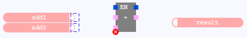
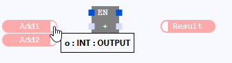
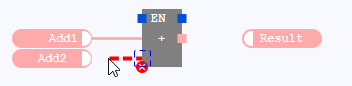
This example illustrates how to connect a call with value fields:
|
1. |
|
|
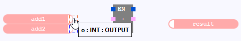
2.a. |
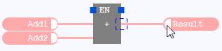
The line will not be created, if you release the mouse button over an empty area. Therefore, drag the line onto another FBD-element, such as the input of a call: While dragging the line, the connection point of the input disappears. This indicates that the line can be created. |
|
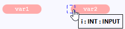
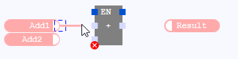
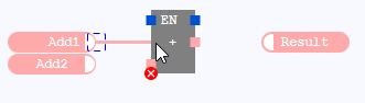
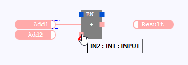
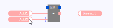
2.b. |
Of course, it is possible to start dragging the line in the other direction. Here the line is highlighted as faulty until an FBD-element is the target.
While dragging the line, the connection point of the input disappears as well. This indicates that the line can be created. |
|
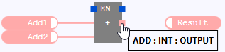
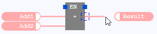
2.c. |
Likewise, it is possible to draw the line from the output of the block to the value field. |
|
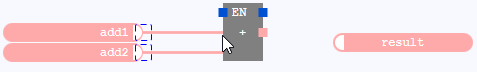
3. |
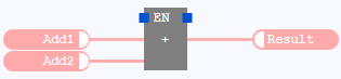
No matter how the lines have been created, the block with the connected value fields looks like this:
|
This example illustrates how to create the lines from the values fields to the block in one go:
|
0. |
Select several connection points while pressing and holding the
Ctrl-key
. Here the outputs of the valued fields are selected. |
|
1. |
Point to one of the selected connection points. |
|
2. |
|
|
3.. |
|