Evaluating SFC elements
Each cycle (when executing the application), logi.CAD 3 checks whether the SFC elements of →SFC network can be evaluated – this check is done in the order as the SFC elements are textually specified within the ST-editor or they are graphically arranged within the FBD-editor (and as indicated by the shown execution order within the FBD-editor).
However, there are rules of evolution vital in the decision whether the SFC element is evaluated in fact. Here are these rules of evolution:
The evolution of the SFC network follows the direct links from the initial →step via one/several →transitions to the successor steps via more transitions to the next successor steps etc.
Moreover, the evolution of the SFC network is regulated as follows:
1.
At the beginning of each cycle, transitions are cleared, if those transitions are enabled and their transition condition is true (see under 3.). The clearing of a transition causes the activation of all the immediate successor steps of this transition.
Mind that no transitions are cleared, if it is the first cycle after a →cold restart. In this case the initial step of the SFC network is active.2.
For each →action that is associated to an active steps, logi.CAD 3 sets an internal input variable action_ACB.action-qualifier to the value TRUE. The name of the input variable depends on the action and the used action qualifier.
If an action qualifier with a duration literal is used, the internal input variable action_ACB.T is set to the value of the duration literal.3.
Depending on the behavior of the action qualifier, an internal output variable action_ACB.Q is set to the value TRUE. Only if this internal output variable action_ACB.Q is set to value TRUE, the statements of the actions are evaluated.
If the statements of several actions can be evaluated at the same time, the actions are evaluated in the order as the actions have been textually specified or graphically arranged.
Applied to the ST- and FBD-editor, this means that the actions are ordered from top to bottom – see the following example 1.
In case of several action blocks that can be evaluated and that are arranged at the same height within the FBD-editor, these action blocks are ordered from left to right. Show the execution order within the FBD-editor in order to see the order of the elements.
4.
At the end of the cycle, logi.CAD 3 determines the transitions to be cleared. All the immediate predecessor steps of such a transition are deactivated at once.
For each action that is associated to these predecessor steps, logi.CAD 3 sets an internal input variable action_ACB.action-qualifier to the value FALSE. Depending on the behavior of the action qualifier, an internal output variable action_ACB.Q is set to the value FALSE. If this internal output variable action_ACB.Q is set to value FALSE, the statements of the actions are not evaluated any longer.The determination of the transitions to be cleared is done in the order as the transitions have been textually specified or graphically arranged.
Applied to the ST- and FBD-editor, this means that the elements are ordered from top to bottom – see the following example 2.
In case of several transitions to be cleared that are arranged at the same height within the FBD-editor, these elements are ordered from left to right.
Show the execution order within the FBD-editor in order to see the order of the elements.Which conditions must be met for the clearing of a transition?
The transition must be enabled.
A transition is enabled, if all predecessor steps of the transition are active.The transition condition of the transition must be true, i.e., it must be evaluated with the value TRUE (or an equivalent).
Mind the following special cases:
If the instance of the POE with SFC network is declared as →retentive (using the keyword RETAIN), the states for the steps and transitions are conserved. Subsequently, it might be possible that transitions are cleared at the beginning of the cycle after a →warm restart because at the end of the cycle (from the previous execution) logi.CAD 3 determined the transitions to be cleared and this information is applied for the warm restart.
If there are several SFC networks within the editor, the above rules are applied for each SFC network. These SFC networks are ordered as follows:
Within the ST-editor, the order of the defined SFC networks is applied, i.e., from top to bottom.
Within the FBD-editor, logi.CAD 3 determines a network to be evaluated. See "Order of networks in FBD".
The following conclusions arise for the evaluation of the SFC elements:
Any activated step is active for at least one cycle.
If a step has zero associated actions, this step waits for a successor transition condition to become true.
If a transition condition for an enabled transition becomes true in one cycle, the associated transition switches only in the following cycle.
An SFC network is not necessarily evaluated completely, before the evaluation of the next SFC network within the editor is started.
![]() The ST-code for the following examples do not quote the complete SFC network. Each SFC network is only created to an extent that is needed to explain the above rules.
The ST-code for the following examples do not quote the complete SFC network. Each SFC network is only created to an extent that is needed to explain the above rules.
Example 1: Determining the active steps in case of simultaneous divergence
A simultaneous divergence exists, when the clearing of a transition leads to the activation of several steps at the same time.
|
ST-code |
TRANSITION t0 FROM S0 TO (S2, S1) := condition_0;END_TRANSITION TRANSITION t1 FROM (S2, S1) TO S3 := ...;END_TRANSITION STEP S1 : act1(N);END_STEPSTEP S2 : act2(N);END_STEP ACTION act2: ...;END_ACTION ACTION act1: ...;END_ACTION |
|
FBD-logic |
|
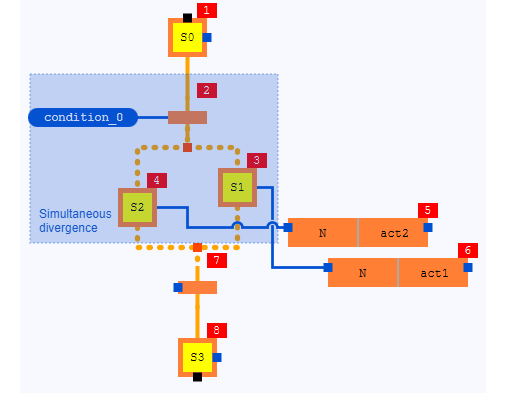
Explaining the evaluation:
If step S0 is active, transition t0 is enabled. The FBD-logic shows the execution order 2 for this transition.
At the end of the cycle, logi.CAD 3 determines the transition to be cleared. If condition_0 is true, t0 is the transition to be cleared and S0 is deactivated.
In the next cycle, t0 is cleared and subsequently S2 as well as S1 are activated. The evaluation of the actions associated to S1 or S2 depends an the action qualifier. Due to the action qualifier N , the internal input variables act1_ACB.N and act2_ACB.N have the value TRUE and subsequently the internal output variables act1_ACB.Q and act2_ACB.Q have the value TRUE. This means that act1 as well as act2 can be evaluated at the same time. Now the same order is caused in the ST-editor as well as to the FBD-editor because of the rule "from top to bottom".
In the ST-code, ACTION act2: ... END_ACTION is specified above ACTION act1: ... END_ACTION.
In the FBD-logic, act2 is more top than act1.
Example 2 for determining the clearing transition in case of divergence
A divergence exists, when several transitions follow one step. The determination of the transitions to be cleared is done because of the order within the ST-code or the FBD-logic.
|
ST-code |
TRANSITION t0 FROM S0 TO S1 := condition_0;END_TRANSITIONTRANSITION t1 FROM S0 TO S2 := condition_1;END_TRANSITIONTRANSITION t2 FROM S1 TO S3 := ...;END_TRANSITIONTRANSITION t3 FROM S2 TO S3 := ...;END_TRANSITION |
|
FBD-logic |
|
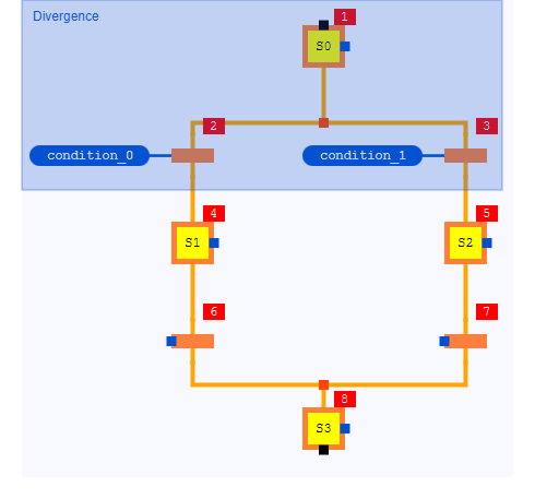
Explaining the evaluation:
If step S0 is active, transitions t0 and t1 are enabled. The FBD-logic shows the execution order 2 for transition t0 and execution order 3 for transition t1.
At the end of the cycle, logi.CAD 3 determines the transitions to be cleared. t0 has priority over t1. Reason: In the ST-code, TRANSITION t0 ... END_TRANSITION is specified above TRANSITION t1 ... END_TRANSITION. In the FBD-logic, the transitions are arranged at the same height – hence, the rule "from left to right" is applied.
If condition_0 is true, t0 is the transition to be cleared and subsequently S0 is deactivated. Then, condition_1 for t1 is not checked anymore because S0 has been deactivated and t1 is not enabled any longer.
In the next cycle, t0 is cleared and subsequently S1 is activated.Only if condition_0 is not true and condition_1 is true, t1 is the transition to be cleared and subsequently S0 is deactivated. In the next cycle, t1 is cleared and subsequently S2 is activated.