Accessing hardware IOs via EC-Engineer
Previous: Configuring the runtime system for using EC-Master
| In this article: |
|---|
In Neuron Power Engineer: Creating a project
If not already done, start Neuron Power Engineer and create a project in which you want to access the hardware IOs.
In EC-Engineer: Connecting to the fieldbus, scanning the fieldbus, exporting ENI-file, requesting ESI-files
Neuron Power Engineer needs the ENI-file ("EtherCAT Network Information" file) in XML-format that is created in →EC-Engineer. The following steps help you to create this ENI-file quickly. If you require more help on using EC-Engineer, see the documentation of EC-Engineer (menu Help within EC-Engineer).
-
Start EC-Engineer. Most likely, the English language is already enabled. If not, do so in order to reproduce the following steps more easily.
How to change the language in EC-Engineer (if German is enabled): menu Einstellungen – Sprache – Choose the English language. -
In EC-Engineer, connect to the EtherCAT fieldbus:
-
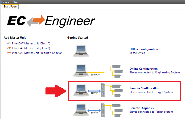
In the Device Editor (Start Page), click TCP/IP — Remote Configuration.
-
Select EtherCAT Master Unit (Class A) and click OK.
-
In the Device Editor under Slaves connected to remote system, enter the IP-address of the PLC (of the Windows PC). Click Select.
If you are using a Windows PC as PLC, mind that you do not enter the IP-address of the reserved network interface card. -
In menu Network, select Scan EtherCAT Network.
Result: The EtherCAT fieldbus is found and scanned because of the entries in fileRTSIO.cfgexisting on the PLC. The project explorer of EC-Engineer displays one item Slave_xxxx (for each terminal on the fieldbus, observe that xxxx is a placeholder for the actual text). -
Make sure that the names of the variables (listed in the Device Editor, tab Variables) are →IEC-identifiers. If the names contain special characters, such as umlauts (
ä,ö,ü) orß, Neuron Power Engineer cannot access the hardware IOs.
-
-
Click Export ENI in the toolbar. Save the ENI-file to any folder.
The ENI-file may have any name. Example:EK1110.xml
Moreover, Neuron Power Engineer needs the ESI-files ("EtherCAT Slave Information" file) in XML-format. A ESI-file contains the EtherCAT device description and can be requested from the device manufacturer.
In Neuron Power Engineer: Dragging ENI-file and ESI-files into the project, creating a global-object, configuring PLC-object and include the GLOBALS section
Change to Neuron Power Engineer and perform the following steps:
-
Drag the ENI-file and the ESI-files into any folder of the Neuron Power Engineer project.
-
Enhance the PLC-object of the project as follows:
-
Open the PLC-object representing the PLC to be addressed.
-
Only required for the alternate scenario (engineering-PC ≠ PLC): Search for the line with
ADDRESSorPORTand replace the entered IP address or port by the appropriate data for your PLC (details: see under "Configuring PLC within PLC-object"). -
Search for the text part
RESOURCE ... ON. Replace the platform entered behindONby the appropriate platform:The PLC is:
Enter this platform:
Example for change line within the PLC-object
a Windows PC
WindowsX86RESOURCE local ON WindowsX86 { ON_CHANNEL := LocalChannel } -
After this line, enter the specification for
IO_IMPORT. Best practice is to use the templateioeprovided by the content assist.
Complete the inserted specification accordingly. Best practice is to use the content assist again whenever a content assist list is provided.Example for a resource with the ENI-file EK1110.xml that has been dragged to the folder 'src' RESOURCE local ON WindowsX86 { ON_CHANNEL := LocalChannel }{ IO_IMPORT PROVIDER := EtherCatProvider, SERVICE := EtherCAT, PARAMS := "src/EK1110.xml", GLOBALS := "src/GlobalsEK1110" }The attribute
GLOBALSspecifies the project-relative path and name for the global-object in which the declarations for the resource-global variables are to be created by Neuron Power Engineer later on. HereGlobalsEK1110with foldersrcis specified.
The attributePARAMSspecifies the project-relative path and name of the ENI-file on which basis the declaration will be created later on. -
After the line with
IO_IMPORT, enter the specification forINCLUDE_GLOBALSand complete it by the name of the global-object as it has been specified for the attributeGLOBALS.
Result, if the global-object does not exist: The specification forINCLUDE_GLOBALSis highlighted as faulty. Ignore this highlighting because the global-object will be created in a later step.Example RESOURCE local ON WindowsX86 { ON_CHANNEL := LocalChannel }{ IO_IMPORT PROVIDER := EtherCatProvider, SERVICE := EtherCAT, PARAMS := "src/EK1110.xml", GLOBALS := "src/GlobalsEK1110" }{INCLUDE_GLOBALS GlobalsEK1110} -
Declare several tasks and label one of those tasks as IO task. See under "Assigning more program types (= creating new instances)" for details on the procedure.
 Take care that the IO-task is responsible for accessing the bus when using the EC-master. If the cycle time is too high, it is possible that the in- and output modules pass into a failsafe state. Subsequently, the application might not receive data from them or write data to them any longer. As experiences has shown, an
 INTERVALin the range of a few milliseconds (e.g. 2 ms) is fitting. Moreover, a high priority (a small number) should be assigned to the IO-task, if the EC-master is used.Example for a test structure with an IO-task TASK DefaultTask(INTERVAL := TIME#500ms, PRIORITY := 38229);{ IO } TASK FastTask(INTERVAL := TIME#2ms, PRIORITY := 2); (* This is the IO-task. *)As an option you are able to specify the IO service for the IO task as this IO service has been defined with the specification for
IO_IMPORT.Example for a test structure with an IO task and IO service TASK DefaultTask(INTERVAL := TIME#500ms, PRIORITY := 38229);{ IO := EtherCAT } TASK FastTask(INTERVAL := TIME#2ms, PRIORITY := 2); -
Declare several program instances and assign the previously declared tasks accordingly:
Example for several program instances PROGRAM Program1 WITH DefaultTask :Program1;PROGRAM AccessIO WITH FastTask:Program1;See under "Assigning more program types (= creating new instances)" for details on the procedure.
-
Save the PLC-object: menu File – Save
-
-
Synchronize the resource with the ENI-file: context menu of the PLC-object, command Synchronize with IO Providers
Result: The specified global-object (here:GlobalsEK1110) is created or updated. The required declarations for the resource-global variables are created in itsGLOBALSsection. These resource-global variables represent the hardware IOs, their physical addresses have already been specified (after the keywordAT).Example for the synchronized content /***** Generated File - DO NOT EDIT - Last updated: 2017-04-24 09:41:41 *****//** generated from RESOURCE "myResource" with the following directive: **//** { IO_IMPORT PROVIDER := EtherCatProvider, SERVICE := EtherCAT, PARAMS := "src/EK1110.xml", GLOBALS := "src/GlobalsEK1110" } **/GLOBALS GlobalsEK1110VAR_GLOBALSlave_1002EL1008Channel1Input AT %IX1.0.0 : BOOL;Slave_1002EL1008Channel2Input AT %IX1.0.1 : BOOL;Slave_1004EL3102Channel1Status AT %IB1.1 : BYTE;Slave_1004EL3102Channel2Value AT %IW1.5 : INT;END_VAREND_GLOBALS -
Do not change the resource-global variables
Neuron recommends to
-
not change the name of the
GLOBALSsection.
Reason: Otherwise the corresponding reference forINCLUDE_GLOBALSwithin the PLC-object cannot be resolved. -
not change these resource-global variables.
Reason: The declarations of the resource-global variables are synchronized and updated, if the command Synchronize with IO Providers is selected (see "Considering changed hardware IOs" for details on the update procedure).
-
In Neuron Power Engineer: Accessing the declared variables within the ST-code
Now you are able to access the declared global variables in the context of →POUs by using →external variables:
-
In the ST-object, declare an external variable – in particular within the declaration of the POU where the access is necessary. Access is possible within the declaration of the program, the declaration of a function block or the declaration of a function.
Example for declarations of external variables
VAR_EXTERNALSlave_1002EL1008Channel1Input : BOOL;Slave_1002EL1008Channel2Input : BOOL;Slave_1004EL3102Channel1Status : BYTE;Slave_1004EL3102Channel2Value : INT;END_VARSee "Declaration of external variables in ST" on the syntax required for the external variable.
-
In the ST-object, use the external variable within the declaration of the POU (e.g. enter it within an assignment).
-
Save the ST-object: menu File – Save
Possibilities for diagnostics
-
If you need information about the EC-Master within your ST-code, Neuron Power Engineer provides blocks for Acontis. Use these blocks accordingly in your ST-object.
-
See "Problems when using EtherCAT field buses" for troubleshooting.
After you have concluded these steps, you can access the hardware IOs within the ST-code.
The article "Considering changed hardware IOs" lists steps to perform when hardware IOs on the EtherCAT-Feldbus are changed. The article "Physical addresses that are based on EC-Master and EC-Engineer" contains background information on the physical addresses.