Connection points
Connection points are the start or end points of lines or nodes on the line itself.
The output connection point (short: output) of an FBD-element is connected by a line to the input connection point (short: input) of the other FBD-element.
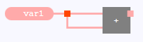
Connected inputs and outputs of an FBD-element are always displayed as part of the line (see the inputs of the ADD block in the following illustration). In contrast to this, connection points on the line or at the start/end of an open line are displayed as red nodes.
![]() Depending on the configuration of your Neuron Power Engineer version, the FBD-editor and its elements might be displayed differently in your Neuron Power Engineer version than illustrated in the IDE documentation. This is the case, if Neuron or the system integrator has activated the smart styling or one of them has changed the styles for the FBD-editor. Subsequently, the illustration in the IDE documentation are symbolic images and the representation in your Neuron Power Engineer version takes precedence for the valid representation. In case of doubts, please contact Neuron or your system integrator.
Depending on the configuration of your Neuron Power Engineer version, the FBD-editor and its elements might be displayed differently in your Neuron Power Engineer version than illustrated in the IDE documentation. This is the case, if Neuron or the system integrator has activated the smart styling or one of them has changed the styles for the FBD-editor. Subsequently, the illustration in the IDE documentation are symbolic images and the representation in your Neuron Power Engineer version takes precedence for the valid representation. In case of doubts, please contact Neuron or your system integrator.
Neuron recommends that you and/or your system integrator do not use yellow shades when designing FBD-elements because the color "Yellow" is used for tracking safe signals when developing safety-related applications. This recommendation applies in particular when you are using the legacy styling. Neuron Power Engineer does not check if colors are already used elsewhere. So the use of the yellow shades by you and/or your system integrator could have the consequence that "yellow" might also identify a non-safe logic as well.
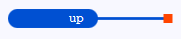
Connection points on a line are necessary in order to create a line fork. A connection point at the start or end of an open line can be used in order to dock the line to other FBD-elements.