Order of networks in FBD
If there are several →networks within the FBD-editor, logi.CAD 3 determines the order of the networks to be →evaluated.
Rules for the order
First logi.CAD 3 checks whether there are networks that can be evaluated according to the →IEC-standard.
Networks can be evaluated, if none of its inputs depends on a network not yet evaluated. Mind the following: Only if inputs for a network are used by other networks as output, the network cannot be evaluated at first.
If all inputs of the network are part of an explicit →feedback loop within the network, this network is put on hold regarding its evaluation after the evaluation of all networks that can be processed. Vice versa the following applies: logi.CAD 3 does not put a network on hold, if this network contains at least one input that can be evaluated or one input that is part or an implicit feedback loop (see example 3 below).Quoting the IEC-standardNo element of a network shall be evaluated until the states of all of its inputs have been evaluated.
The evaluation of a network element shall not be complete until the states of all of its outputs have been evaluated.
The evaluation of a network is not complete until the outputs of all of its elements have been evaluated, even if the network contains one of the execution control elements.
Implementer-specific realization
The IEC-standard defines that i t shall be possible for the user to utilize an implementer-specific means to determine the order of execution of the elements in an explicit →feedback loop, for instance by selection of a feedback variable.
Therefore, logi.CAD 3 attempts to resolve a feedback loop using feedback variables. But if there is no variable in the feedback loop, the calls are used to resolve the feedback loop.
Subsequently, logi.cals recommends that you use such feedback variables in feedback loops. On the one hand, you can better control the execution order of the network elements by using a feedback variable. And on the other hand, you remain compliant with the IEC-standard, since feedback loops without a feedback variable are not considered in the IEC-standard.
Mind the following: If a variable is used as array index itself or within the array index, logi.CAD 3 considers this variable as an input as well.
If logi.CAD 3 determines that
only one of the networks can be evaluated, the statements of this network are evaluated.
several networks or not one of the networks can be evaluated, logi.CAD 3 determines the graphical position of these networks. Networks are ordered from "top left to bottom right". logi.CAD 3 evaluates the statements of the network with the statement most top/left (top is applied before left).
Mind that there are 2 types of statements:
Call statements (short: →calls): Calls are created by positioning a →function block or a →function.
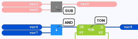
Here you see calls of the SUB function, AND function and TON function block respectively:
For calls, the crucial factor is the upper left corner of the call (without a possibly displayed instance name).The call of the upper NOT block ranks before the lower one (top is applied before left):

The call of the left NOT block ranks before the right one:

 In principle, SFC elements of an →SFC network behave like calls within the network. But observe that SFC elements are evaluated according to predefined rules of evolution
Assignment statements (short: →assignments): Assignments are created by positioning a value field and by connecting it with a call or another value field.
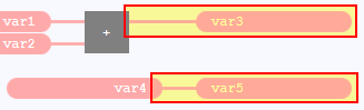
Here you see assignments to the variable var3 and var5 respectively:
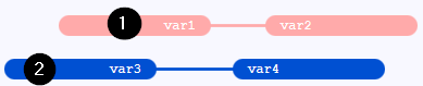
For assignments, the crucial factor is the position of the input of the value field.The value field with var1 is the statement most top/left. Hence, the statements of the network with the pink value fields are evaluated before the ones of the network with the blue value fields.
The value field with var4 is the statement most top/left. Hence, the statements of the network with the blue value fields are evaluated before the ones of the network with the pink value fields.
The value field with var5 is the statement most top/left. Hence, the statements of the network with the blue value fields are evaluated before the ones of the network with the pink value fields.

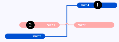
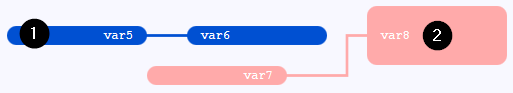
The value field with var5 is still the statement most top/left although the value field with var8 seems to be positioned more top. The crucial factor is that the input of the value field with var5 is most top/left. Hence, the statements of the network with the blue value fields are evaluated before the ones of the network with the pink value fields.
After the network has been evaluated completely, the rules are applied again to determine the next network to be evaluated (starting with the 1. step).
![]() The rules in this article and the following examples apply to the default configuration of
logi.CAD 3
.
Different rules are applied, if you have used the start option lc3.fbdStatementSortLC32 to activate the execution order modeled after the predecessor product logi.CAD/32. The behavior modeled on the predecessor product corresponds to the behavior in the predecessor product with the logi.CAD/32 environment variable LC32_SORTORDER_TAR_DEP_CHECK=1. Details about the rules of the execution order for logi.CAD/32 can be found in the online help of logi.CAD/32. the information about LC32_SORTORDER_TAR_DEP_CHECK=1 can be found in the documentation for administrators of the predecessor product (in the article "Defining Processing Variant Concerning Variables Used as Array Index").
The rules in this article and the following examples apply to the default configuration of
logi.CAD 3
.
Different rules are applied, if you have used the start option lc3.fbdStatementSortLC32 to activate the execution order modeled after the predecessor product logi.CAD/32. The behavior modeled on the predecessor product corresponds to the behavior in the predecessor product with the logi.CAD/32 environment variable LC32_SORTORDER_TAR_DEP_CHECK=1. Details about the rules of the execution order for logi.CAD/32 can be found in the online help of logi.CAD/32. the information about LC32_SORTORDER_TAR_DEP_CHECK=1 can be found in the documentation for administrators of the predecessor product (in the article "Defining Processing Variant Concerning Variables Used as Array Index").
The differences betwwen
logi.CAD/32
and
logi.CAD 3
in the default configuration are specified in the description "Differences: Predecessor product to current product
", search for the lines with the text "feedback loops" and "execution order" in this description.
Examples for the order
The order of the networks can be deduced from the execution order (= number displayed within the red rectangle) that is shown for the statements of the networks in the examples.
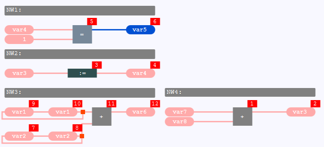
Example 1: Dependent and several evaluable networks
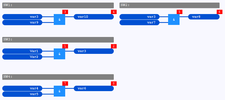
The networks are evaluated in this order:
NW3 – Reason: The networks NW1 and NW2 cannot be evaluated because the variable var3 depends on network NW3. In contrast, the inputs of NW3 as well as of NW4 do not depend on any other network. As NW3 is top of NW4 (in detail: the input of the value field with var1 in NW3 is positioned top of the value field with var4 in NW4 ), NW3 is evaluated as the first network.
NW1 – Reason: var3 is evaluated after the evaluation of NW3. This means that NW1, NW2 and NW4 can be evaluated now. As NW1 is top of NW4 and left of NW2 (in detail: the input of the value field with var3 in NW1 is the statement most top/left ), NW1 is evaluated as the next network.
NW2 – Reason: NW2 and NW4 can be evaluated. As NW2 is top of NW4 (in detail: the input of the value field with var3 in NW2 is positioned top of the value field with var4 in NW4 ), NW2 is evaluated as the next network.
NW4 – Reason: Only NW4 can be evaluated.
Example 2: Dependent networks with a variable as array index
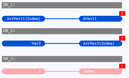
The networks are evaluated in this order:
NW_3 – Reason: The networks NW_1 and NW_2 cannot be evaluated because the variable Index that is used as array index in these networks depends on network NW_3. Thus, only NW_3 can be evaluated.
NW_1 – Reason: Index is evaluated after the evaluation of NW_1. This means that NW_1 and NW_2 can be evaluated now. As NW_1 is top of NW_2 (in detail: the input of the value field with ArrVar11[Index] is the statement most top/left ), NW_1 is evaluated as the next network.
NW_2 – Reason: Only NW_2 can be evaluated.
The following example differs from the above example by the value fields ArrVar3[Index+1] in NW_A and NW_B:
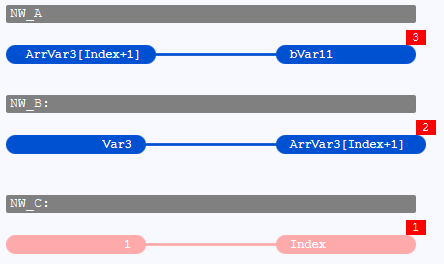
The networks are evaluated in this order:
NW_C – Reason: Neither the network NW_A nor the network NW_B can be evaluated. NW_A cannot be evaluated because ArrVar3[Index+1] depends on the network NW_B (besides, the variable Index that is used within the array index in NW_A depends on network NW_C). NW_B can neither be evaluated because the variable Index that is used within the array index in NW_B depends on network NW_C. Thus, only NW_C can be evaluated.
NW_B – Reason: After Index has been evaluated, only NW_B can be evaluated. In contrast to the above example, it is still not possible to evaluate NW_A because ArrVar3[Index+1] still depends on network NW_B.
NW_A – Reason: Only NW_A can be evaluated.
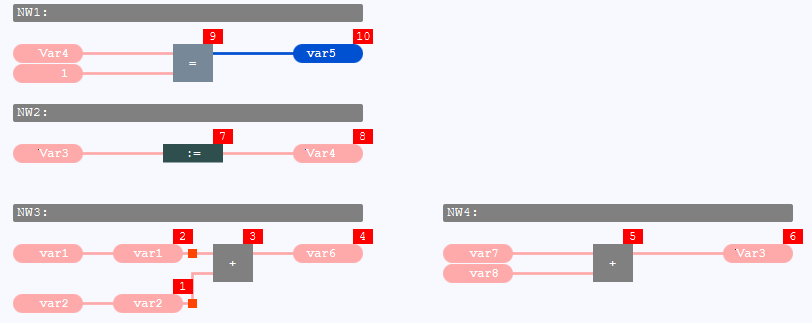
Example 3: Networks without and with feedback loop
The networks are evaluated in this order:
NW4 – Reason: The networks NW1 and NW2 cannot be evaluated because their inputs (= variable var4 or var3) depend on other networks. In contrast, the inputs of NW3 as well as of NW4 do not depend on any other network. However, all inputs of NW3 are part of an explicit feedback loop within NW3 resulting in the fact that the evaluation of NW3 is put on hold. Subsequently, only NW4 is left for evaluation.
NW2 – Reason: var3 is evaluated after the evaluation of NW4. This means that NW2 can be evaluated. NW3 can be evaluated as well but its evaluation is put on hold again due to the feedback loop.
NW1 – Reason: var4 is evaluated after the evaluation of NW2. This means that NW1 can be evaluated. NW3 can be evaluated as well but its evaluation is put on hold again due to the feedback loop.
NW3 – Reason: Only NW3 can be evaluated.
The following example differs from the above example by the inputs of NW3 being part of an implicit feedback loop:
The networks are evaluated in this order:
NW3 – Reason: The networks NW1 and NW2 cannot be evaluated because their inputs (= variable var4 or var3) depend on other networks. In contrast, the inputs of NW3 as well as of NW4 do not depend on any other network. Here NW4 is not put on hold because none of the inputs is part of an explicit feedback loop. As NW3 is more left than NW4 (in detail: the input of the value field with var1 in NW3 is positioned more left than the value field with var7 in NW4 ), NW3 is evaluated as the first network.
NW4 – Reason: Only NW4 can be evaluated.
NW2 – Reason: var3 is evaluated after the evaluation of NW4. This means that NW2 can be evaluated.
NW1 – Reason: var4 is evaluated after the evaluation of NW2. This means that NW1 can be evaluated.
Note: This order of the networks also applies, if just one input of NW3 is a part of an implicit feedback loop and just one input of NW3 is part of an explicit feedback loop. Hence the networks are evaluated in this order: NW3, NW4, NW2 and finally NW1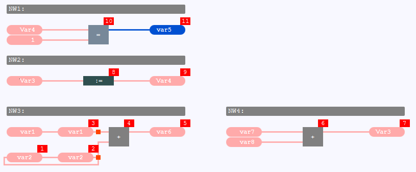
![]() But mind that there is a different order of the statements within the network NW3 (see "Order of statements within an FBD-network" for how logi.CAD 3 determines the order within the network).
But mind that there is a different order of the statements within the network NW3 (see "Order of statements within an FBD-network" for how logi.CAD 3 determines the order within the network).