Comment fields
Use comment fields in the FBD-editor to have comments at any position within the function logic.
logi.CAD 3 provides the following types of comment fields :
![]() Depending on the configuration of your logi.CAD 3 version, the FBD-editor and its elements might be displayed differently in your logi.CAD 3 version than illustrated in the IDE documentation. This is the case, if logi.cals or the system integrator has changed the styles for the FBD-editor. Subsequently, the illustration in the IDE documentation are symbolic images and the representation in your logi.CAD 3 version takes precedence for the valid representation. In case of doubts, please contact logi.cals or your system integrator.
Depending on the configuration of your logi.CAD 3 version, the FBD-editor and its elements might be displayed differently in your logi.CAD 3 version than illustrated in the IDE documentation. This is the case, if logi.cals or the system integrator has changed the styles for the FBD-editor. Subsequently, the illustration in the IDE documentation are symbolic images and the representation in your logi.CAD 3 version takes precedence for the valid representation. In case of doubts, please contact logi.cals or your system integrator.
logi.cals recommends that you and/or your system integrator do not use yellow shades when designing FBD-elements because the color "Yellow" is used for tracking safe signals when developing safety-related applications. logi.CAD 3 does not check if colors are already used elsewhere. So the use of the yellow shades by you and/or your system integrator could have the consequence that "yellow" might also identify a non-safe logic as well.
Comment field within the drawing field
It is possible to attach a comment field to a certain FBD-element or to position it without any attachment within the drawing field.
Representation
Example for 3 comment fields (without any attachment) and one comment field that is attached to the →call of an RS block:
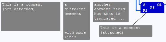
The assignment of the comment field is represented by a direct line. Use attached comment fields in order to evaluate information by using dynamic texts within the attached comment fields.
Comment field within the interface for a block
Comment fields that are created within the interface of a block are also identified as internal comment fields.
Representation
Example for a comment field within the interface editor:
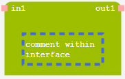
The comment field within the interface editor has been selected in the above example so that it is easier to detect the comment field (by means of the selection frame).