Physical addresses that are based on EC-Master and EC-Engineer
The following information are not necessary to access the hardware IOs via EC-Engineer. This article contains background information how the physical addresses in logi.CAD 3 are formed :
|
|
Character |
Meaning |
|
1. |
% |
initiates the address |
|
2. |
prefix for location |
defines the location |
|
|
I |
input |
|
|
Q |
output |
|
|
M |
memory |
|
3. |
prefix for size |
defines the size |
|
|
X or none |
bool (single bit) |
|
|
B |
byte (8 bits) |
|
|
W |
word (16 bits) |
|
|
D |
double word (32 bits) |
|
|
L |
long word (64 bits) |
|
4. |
one or more →unsigned integers Restriction
Depending on the PLC platform and the IO provider,
logi.CAD 3 supports max. 5 levels. C
ontact your system integrator for details.
|
defines the address |
Example: The following information (shown in rectangles) from EC-Engineer result in the physical address %IB1.1.0 which can be used for a variable with type BYTE
:
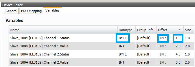
Keep in mind:
The column Datatype indicates the size (the data type) of the IO.
The left-hand information in column Offset indicates where is the IO located. IN : represents an input, OUT : an output.
The right-hand information in column Offset indicates the address of the IO. This address is added after 1. (1 is the device ID entered in file RTSIO.cfg when the runtime system has been configured).
The information is displayed in EC-Engineer, if it is connected to the EtherCAT fieldbus:
In the project explorer of the EC-Engineer, select an entry Slave_xxxx.
In the Device Editor, go to tab Variables.