The dos and don'ts when working
This article contains a summary of the items that you must observe when working with logi.CAD 3:
If you need details on any item, click the link listed to the right of the item. This takes you to an article that usually contains a warning or a note (identified by icon ![]() or
or ![]() ) specifying the item.
) specifying the item.
If you have more questions regarding an item and there are no information to be found in the user documentation of logi.CAD 3, contact the support team of logi.cals.
Other useful links:
|
step-by-step instructions |
|
|
other actions |
|
|
fast searching within the user documentation |
When installing
|
Observe: |
Details under: |
|
no special characters in installation path of logi.CAD 3 |
|
|
no installation path incl. compiler path with more than 255 characters |
Additionally, observe for target systems:
|
if Raspberry Pi is used as PLC: version for →runtime system to be installing |
|
|
if a 64 bit system of Linux is used as operating system: have certain commands executed in a terminal window |
When starting
|
Observe: |
Details under: |
|
allowing access when Windows security alerts are displayed |
Starting the development environment and the runtime environment |
|
enter a new workspace per start of logi.CAD 3 (outside the installation directory of logi.CAD 3) |
Starting the development environment and the runtime environment, |
|
start logi.CAD 3 in another language |
How do I change the language for the user interface?, |
When creating projects
|
Observe: |
Details under: |
|
no blanks or special characters in project name and location |
|
|
do not create projects in the workspace |
|
|
linked folders become "real" folders after importing |
When working in the project explorer
|
Observe: |
Details under: |
|
do not manipulate →libraries |
|
|
do not change file extensions |
|
|
do not export linked folders to archive files |
|
|
modifications outside logi.CAD 3 make "Refreshing" necessary |
Viewing state information on PLC, |
|
Show the folders src-gen or target only if you need to solve a problem. |
for general information: Project explorer to manage project |
When creating the application
General programming guidelines
No identification of infinite loops and missing abort conditions respectively
Infinite loops as well as missing abort conditions are not identified by logi.CAD 3. Provide correct abort conditions (e.g. by using IF-statements) to prevent infinite loops.
|
Example for infinite loop without abort condition |
Example for infinit loop with an abort condition |
PROGRAM Test1 MyFun(1);END_PROGRAMFUNCTION MyFun VAR_INPUT In : INT; END_VAR MyFun(In + 1);END_FUNCTIONIf you load such applications onto the PLC anyway, the →runtime system might be terminated. In this case, a window with the following text appears: RTSLoader.exe stopped workingSolutions are listed in the troubleshooting article: PLC cannot be addressed. The runtime system is slow to respond or does not respond at all. |
PROGRAM Test1 MyFun(1);END_PROGRAMFUNCTION MyFun VAR_INPUT In : INT; END_VAR IF In < 10 THEN MyFun(In + 1); END_IF;END_FUNCTION |
No check of recursions
Recursions for →functions and →methods are not forbidden or checked by
logi.CAD 3
. Nevertheless, do not call a function/method from within itself and avoid 2 (or more) functions/methods calling each other (= mutual recursion) within your application.
Mind that recursions of functions/methods might cause unexpected results when your application is executed. For example, the application might be executed in an infinite loop and/or the →runtime system
might not respond anymore.
![]() In contrast to this, recursions for →function blocks are recognized and highlighted as faulty.
In contrast to this, recursions for →function blocks are recognized and highlighted as faulty.
When creating the application in ST
|
Observe: |
Details under: |
|
no check of invalid connections by logi.CAD 3 (e.g. when using the numeric functions, such as the EXPT block, or when using the MUL_TIME block) |
Numeric functions |
|
do not use keywords for identifiers |
|
|
ST-elements, supported at present |
articles within section "Supported ST-syntax" |
|
Expressions with more than 20 operands/operators influence the performance. |
|
|
no detection of mathematical errors when assigning expressions |
|
|
The following ST-elements are supported with restrictions:
|
|
|
a collection of things when using in-out variables (= VAR_IN_OUT) |
|
|
In case of STRING variables:
|
|
|
no identification of infinite loops in case of REPEAT and WHILE statements |
|
|
The following data types are not supported: LTIME , WSTRING , WCHAR , LDATE_AND_TIME , LTIME_OF_DAY und LDATE |
|
|
inaccuracies for floating-point numbers (REAL and LREAL values) |
Depending on the used target system:
|
Observe: |
Details under: |
|
Other provided system blocks:
|
When creating the application in FBD
|
Observe: |
Details under: |
|
possible to declare one POU within an FBD-object |
|
|
other displayed colors for data types and/or other displayed FBD-elements (as illustrated in the IDE documentation) |
Also, observe the items under " When creating the application in ST ". These might be relevant for a FBD-logic, too.
When creating the application in LD
|
Observe: |
Details under: |
|
possible to declare one POU within an LD-object |
|
|
contacts/coils that are not provided in functions |
Also, observe the items under " When creating the application in ST ". These might be relevant for a ladder diagram, too.
When creating blocks with C-code
Possible problems for an application due to name conflicts in the C-code (e.g. in case of vendor blocks and import of a Simulink model).
If you are using not-unique names in the →C code and they are available in the global namespace, conflicts might be caused when using several blocks with such C code. However, these conflicts may not cause errors/warnings when building the application. As a result, the runtime behavior might be affected in an undesirable way.
Example: The Values of Variables view displays 2 variables to which the return value of POU1 an POU2 respectively has been assigned. The value for Program1.rc2 displays the unexpected value 1 while the value 2 is actually assigned in the C-code. The problem is caused due to the same name RESULT within the C-code of the 2 vendor blocks POU1 and POU2.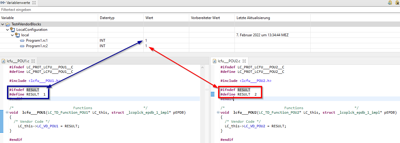
Additional information: This problem is valid for:
→vendor blocks that you have created
vendor blocks that have been created when importing a Simulink model
vendor blocks that have been created when migrating from the predecessor product logi.CAD/32 to logi.CAD 3
blocks with C-/C++-code that you created based on an ST-interface (see "Creating the interface for a C-block or C++-block (deprecated)")
Workaround 1: Use POU-unique names (when possible, project- and POU-unique) for all C-identifiers that are available in a global namespace. If you are importing a Simulink model, the best practice is to use the unique names already in the Simulink model.
Workaround for the above example: Now the Values of Variables view displays the expected value 2 for Program1.rc2 because POU-unique names have been used within the C-code.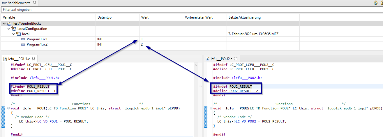
Workaround 2: If you provide the blocks with C-code in a library, specify the blocks in the library configuration with DEPLOY:=OBJECT (see under " Declaration of the contents of the library " for details on DEPLOY:=OBJECT ). As a result, the binary code for the POU is built separately when the library is created.
Used system blocks
Accuracy and behavior of mathematical functions
Mathematical functions that are processing floating-point numbers (REAL, LREAL) might return different results on different target system s – in particular, if the result of the function is located within the threshold of the data type. These different inaccuracies of the mathematical functions is caused by the following factors:
the →target system itself,
the compiler used for the target system and
the configured optimization flags for the compiler.
Do not use blocks/variables with LREAL for Controllino or Arduino Nano
If you create an application for a →Controllino or an →Arduino Nano, avoid the usage of blocks/variables processing/returning LREAL values. The usage of such blocks/variables is possible but the LREAL values are processed with the accuracy of REAL values.
Observe that the DIV_TIME block is internally always using LREAL values.
Behavior of convert blocks in case of a range of values not overlapping
TRUNC blocks and other convert functions with a REAL/LREAL input might return different results for different compilers and on different target system s as well, if the connected value is not within the range of values overlapping for the data type of the input and for the data type of the return value . These different results are caused by the following factors:
the compiler used for the target system and
the →target system itself
Therefore, enter code in your application to detect when the range of values is not overlapping (e.g. IF-statements
in the ST-code). See under "Convert functions" and "ConvertEnh functions" which of the convert functions provide a REAL/LREAL input.
Known examples:
|
Target system |
Result of the mathematical function TRUNC_DINT(REAL#3.402823466e+38); |
|
→logi.RTS for Windows |
-2147483648 |
|
2147483647 |
|
|
RTOS32 compiler |
-2147483648 |
The RTOS32 compiler reports an error in case of a specific division.
If you are using the RTOS32 compiler, avoid a specific division (see the following example) in your application.
PROGRAM Program1 DIV(DINT#-2_147_483_648, DINT#-1);END_PROGRAMWhen building the application, the compilers report the expected warning overflow in constant division, undefined behavior. But the RTOS32 compiler also reports an error divide or mod by zero. Other compilers do accept the code – only the mentioned warning is reported. To avoid the reporting of the error when using the RTOS32 compiler, do not use a division with the above-mentioned negative integers.
|
Observe: |
Details under: |
|
system blocks based on the →IEC-standard but with restrictions:
|
|
|
system blocks based on the →IEC-standard but with enhancements:
|
|
|
system blocks in addition to the →IEC-standard:
|
|
When defining settings for the PLC
|
Observe: |
Details under: |
|
max. 32 tasks per resource |
|
|
restrictions when scheduling several program types |
|
|
restrictions for VAR_CONFIG sections |
When testing the application
|
Observe: |
Details under: |
|
display in Instances view: just base type for array variables |
|
|
changing value for variable ≠ forcing |
|
|
used target system might influence literals entered/displayed in logi.CAD 3 |
Additionally, observe for target systems:
|
default timer resolution for most Linux operating systems |
When debugging the application
|
Observe: |
Details under: |
|
Control flow debugging: Debugging the application by setting breakpoints |
|
When creating the application in →C or →C++
|
Observe: |
Details under: |
|
when creating projects, use different position for C/C++ projects |
Die gleiche Positon für C-/C++-Projekte bzw. andere Projekte verursacht Probleme |
|
When using the Raspberry Pi
|
Observe: |
Details under: |
|
requirements for SD card |
|
|
version for runtime system to be installed |
|
|
power supply for Raspberry Pi |
|
|
activated default locale en_GB.UTF-8 UTF-8 |
|
|
in case of data transfer via MQTT: controlling the connection for TCP port |
|
|
default timer resolution for most Linux operating systems (e.g. Raspbian) |
When accessing hardware IOs via EC-Master and EC-Engineer
|
Observe: |
Details under: |
|
when preparing the environment: conditions for the network interface card |
|
|
installing runtime system under Windows (contains an evaluation version of EC-Master) |
|
|
do not change the resource-global variables |
When changing the layout
|
Observe: |
Details under: |
|
different steps for moving/docking views/editors |
Moving or docking views and editors, |
Performance
|
Observe: |
Details under: |
|
in case of performance issues |