SFC elements in drawing field
Moreover, the drawing field of the →graphical FBD-editor displays the following SFC elements as graphical symbols:
Enhancement to IEC-standard
The parallel usage of SFC elements and FBD-elements within the same POU, such as steps and parallel assignments by calls of blocks or value fields, is an enhancement to the →IEC-standard. According to the IEC standard, it is not possible to combine SFC elements with other FBD logic within the same POU.
Using/Creating SFC networks efficiently and correctly
Knowledge about programming step sequences is essential when creating SFC networks.
It is possible to create several SFC networks within →programs and →function blocks.
Unsafe or unreachable SFC networks or such ones with a deadlock are not detected or prevented by logi.CAD 3.
Unsafe SFC networks might be caused, if there are more divergences than convergences in the SFC network. Unreachable branches in the SFC network might be caused, if there are different types of a divergence and of a convergence. In case of SFC networks with a deadlock, each SFC network is waiting for an operation of the other SFC network but this operation will never be executed.
If you require more details on such SFC networks, see the IEC-standard and/or the Technical Report IEC TR 61131-8 (Programmable controllers – Part 8: Guidelines for the application and implementation of programming languages) and search for "unsafe SFC", "unreachable SFC" and "deadly embrace".
Example for an FBD-logic with a step sequence:
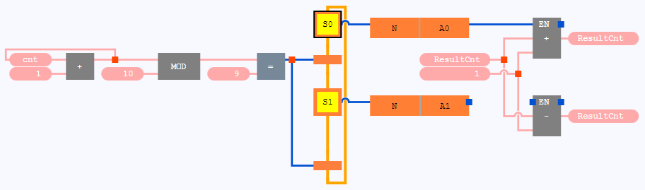
See under "Creating SFC networks in FBD" for information how to create the respective SFC-element. See "Creating step sequences in FBD" for more examples of step sequences.