Lines
A line connects FBD-elements, such as →value fields, with other FBD-elements.
Usually, a line leads from the output connection point (short: output) of one FBD-element to the input connection point (short: input) of the other FBD-element.
Open lines are possible – an open line is a line that does not start and/or end with an FBD-element.
A line might consist of different orthogonal parts that are automatically created.
Representation
Color/style of a line is determined by the data type that is valid for the output.
![]() Depending on the configuration of your logi.CAD 3 version, the FBD-editor and its elements might be displayed differently in your logi.CAD 3 version than illustrated in the IDE documentation. This is the case, if logi.cals or the system integrator has changed the styles for the FBD-editor. Subsequently, the illustration in the IDE documentation are symbolic images and the representation in your logi.CAD 3 version takes precedence for the valid representation. In case of doubts, please contact logi.cals or your system integrator.
Depending on the configuration of your logi.CAD 3 version, the FBD-editor and its elements might be displayed differently in your logi.CAD 3 version than illustrated in the IDE documentation. This is the case, if logi.cals or the system integrator has changed the styles for the FBD-editor. Subsequently, the illustration in the IDE documentation are symbolic images and the representation in your logi.CAD 3 version takes precedence for the valid representation. In case of doubts, please contact logi.cals or your system integrator.
logi.cals recommends that you and/or your system integrator do not use yellow shades when designing FBD-elements because the color "Yellow" is used for tracking safe signals when developing safety-related applications. logi.CAD 3 does not check if colors are already used elsewhere. So the use of the yellow shades by you and/or your system integrator could have the consequence that "yellow" might also identify a non-safe logic as well.
Examples for the representation:
Values fields that are connected with a line:

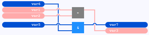
Calls and values fields that are connected with lines:
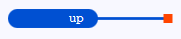
Value field with an open line:
By default, Boolean lines are emphasized within an FBD-editor with →instance context:
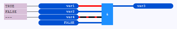
Boolean lines are lines that are connected to FBD-elements containing or representing a →variable of →data type BOOL. or a →Boolean literal . The emphasizing of Boolean lines has the following meaning:
A thick, red line indicates the value TRUE (or an equivalent).
A thick, dark-blue line indicates the value FALSE (or an equivalent).
A thick line dashed in black and red is indicating that no value could be requested for the line. A possible reason for this is that the current state of the application has not been loaded onto the PLC yet. This means for the illustration:: The variables var1, var2 and var3 already exist on the PLC, but not the variable var4.
![]() When animating a Boolean line for a variable, logi.CAD 3 is using the value that exists on the →PLC. However in case of a Boolean literal, logi.CAD 3 is using the value directly from the logic. See "Example: Effect of a changed Boolean literal onto the animation".
When animating a Boolean line for a variable, logi.CAD 3 is using the value that exists on the →PLC. However in case of a Boolean literal, logi.CAD 3 is using the value directly from the logic. See "Example: Effect of a changed Boolean literal onto the animation".
Actions for lines
Page:Inserting a call of a block or value field into existing lines
Page:Connecting an already connected line to a different FBD-element
Page:Moving FBD-elements
![]() You might want to use connectors and continuations to replace some of the lines.
You might want to use connectors and continuations to replace some of the lines.