Creating the visualization project by using the PROCON-WEB IoT Designer
This article contains a tutorial on how to use the PROCON-WEB IoT Designer with the visualization data that has been exported in logi.CAD 3.![]() See the documentation on the PROCON-WEB Designer by GTI control, if you need details on some instructions or you want to learn more about the possibilities of the designer.
See the documentation on the PROCON-WEB Designer by GTI control, if you need details on some instructions or you want to learn more about the possibilities of the designer.
Installing and starting the PROCON-WEB IoT Designer
Double-click the file PWeb_x.y.z-IOT_Full.exe and follow the instructions of the installation program.
This file can be obtained from logi.cals (x.y.z is a placeholder for the respective version number).Attach the USB-stick to an USB-port in order to activate the PROCON-WEB license.
The USB stick can be obtained from GTI control. Without a license, PROCON-WEB IoT Designer can be operated as demo version only.Select the item PROCON-WEB x.y Designer 32Bit in the Windows start menu (x.y is a placeholder for the respective version number).
Creating the visualization project
How to create the visualization project in the PROCON-WEB IoT Designer (called "Designer" in the following text) and how to use the visualization data from logi.CAD 3 in the Designer:
In the ribbon pane, click New Project, enter a project name, select IoT under Target type and click OK.
Result: The project tree provides the PROCON-WEB functions.Determine the communication for the process:
In the project tree, expand the item Process connection.
Select the item Tag.
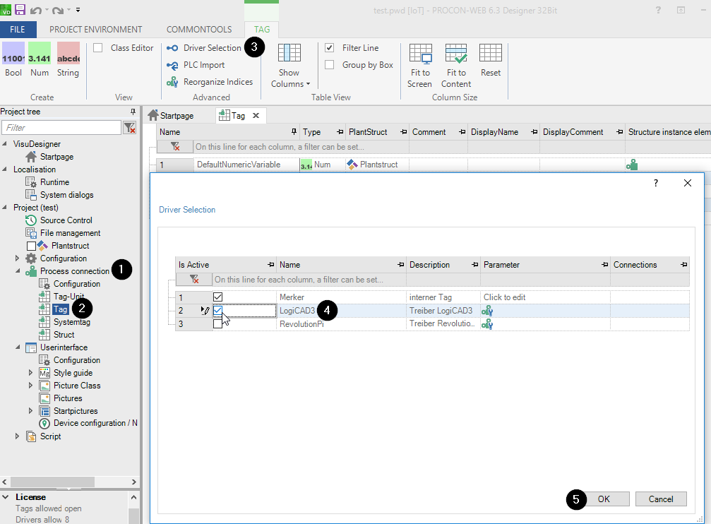
Result: The main area displays the tab Tag with 5 predefined process variables. Moreover, the ribbon pane switches to the tab TAG.In tab TAG, click Driver Selection.
In the dialog, select LogiCAD3 and click OK.
Import the variables from logi.CAD 3 into the Designer:
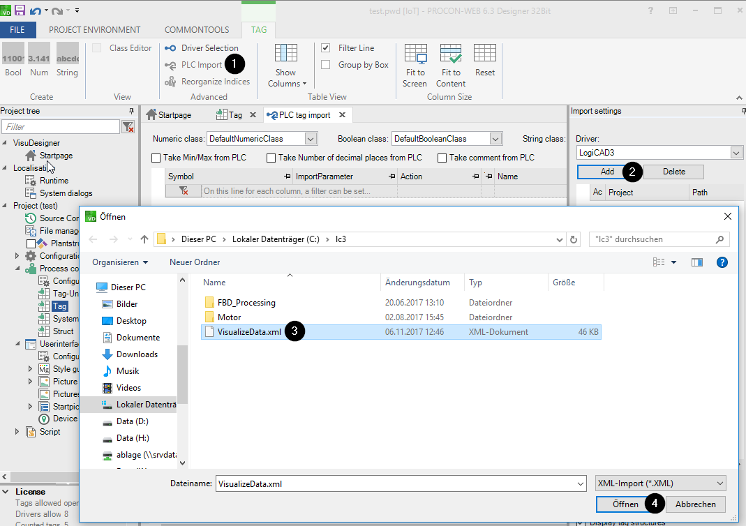
In tab TAG, click PLC Import.
Result: The main area displays the tab PLC tag import. Right of this tab, the area Import settings with the driver LogiCAD3 is displayed.In the area Import settings, click Add..
In the dialog, select the XML-file containing the visualization data of logi.CAD 3 and click Open.
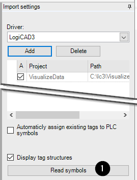
Result: The file is listed in the area Import settings.
Click Read symbol in the lower area of Import settings.
Result: The process variables are listed in the tab PLC tag import.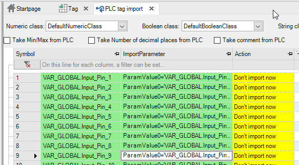
Select the variables required for the visualization. Open the context menu for these variables and select the command Import now.
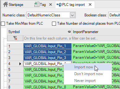
Result: Now the process variables have been created within the Designer and are visible within the tab Tag.
Create the first process image in which the variables from logi.CAD 3 will be visualized:
In the project tree, expand the item Userinterface and the child item Startpictures.
Double-click the image Start that is provided in a new project by default.
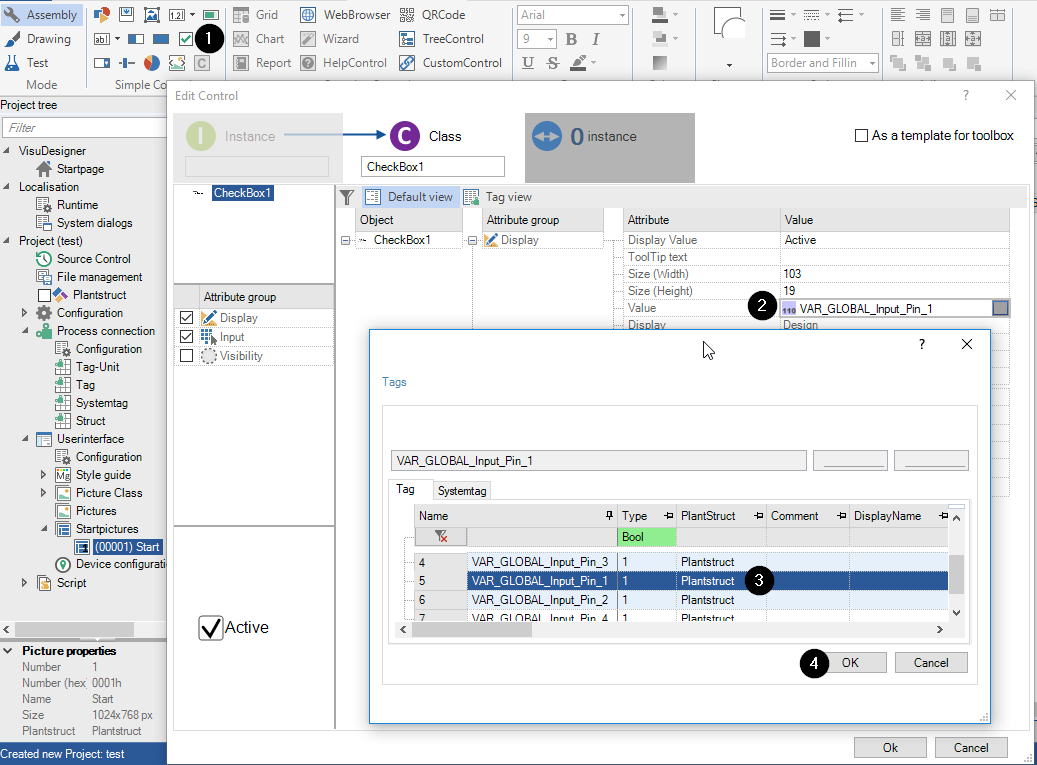
Result: The main area displays the editor for Start. Moreover, the ribbon pane switches to the tab PICTURE EDITING.In the tab PICTURE EDITING, click the button for the required control, e.g. click Checkbox or Button.
In the dialog Edit Control, define the appropriate settings (e.g. the text for the control). It is also possible to connect the control with a process variable.
Control
Connection possible at
Example
Checkbox
setting Value
Button
setting Action Bool 1
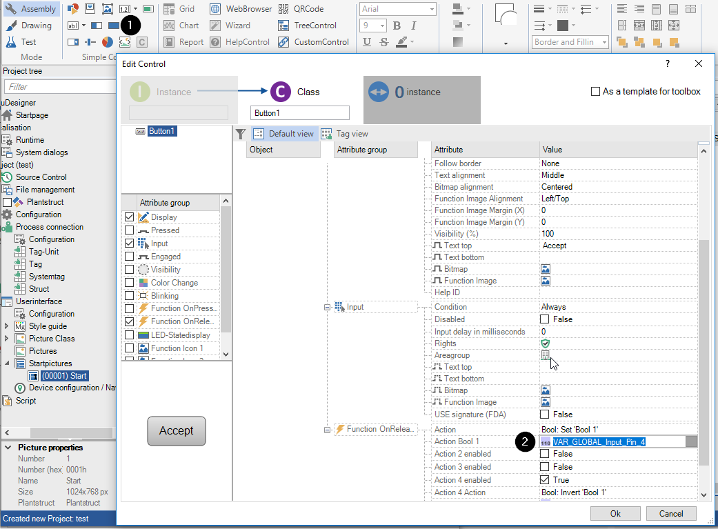
 Selecting the button within the line of the setting will display a dialog in which you are able to select a process variable – see the example for the checkbox.
Position the controls within the process image.
Save the visualization project within the Designer: e.g. menu File – Save Project