Monitoring and changing values in viewer or editor
The Values of Variables view is a central location in order to monitor values on the →PLC. But logi.CAD 3 provides the possibility to monitor and change the values within the ST-code or the FBD-logic as well.
Perform the following steps (follow the links, if you need more details on the appropriate step):
Monitor the values within the ST-viewer or by using OLT-fields within the FBD-editor and the ladder diagram.
More information can be found under:
Missing values
If the values for some variables are not displayed, this might be caused for one of the following causes
:
The target system does not support the query of DMA variables.
The target system cannot provide the values due to other reasons (siehe "Properties and restrictions specific to the target system") or no correct connection to the target system is possible (see No connection to the target system, but there are error messages).
The variable is a →reference variable that has been initialized with value NULL . logi.CAD 3 is not able to display values for such variables.
The variable is a variable based on an →interface . logi.CAD 3 is not able to display values for such variables.
logi.CAD 3 has been started with the option LC3useRTS3MetaData=false. – In this case, logi.CAD 3 is not able to display values for variables. Solution: Make sure that the generation of metadata is enabled before logi.CAD 3 is started.
Go to the folder where you installed logi.CAD 3.
Locate the file logiCAD3.ini and open it in a text editor.
Search for -DLC3useRTS3MetaData.
If this configuration variable is defined with value false, define the value true.
Example for corrected lines...-Xms256m-Xmx6144m-DLC3useRTS3MetaData=true By default, the generation of metadata is activated in logi.CAD 3. However, the generation has been deactivated due to -DLC3useRTS3MetaData=false (after the option -vmargs).
Save the file.
Details on the ST-viewer
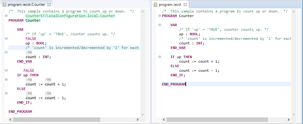
The ST-viewer provides an additional line above a variable. This line displays the current value of the variable at the end of the cycle.
Observe the following, when you are using the ST-viewer:
The operation of the ST-viewer is analogous to the one of the ST-editor – with the exception of the following differences:
The ST-code cannot be changed within the ST-viewer.
The value of a variable can be changed within the ST-view as follows: Position the cursor onto the variable, select the context menu command Set Instance Value or press the Enter-key and enter a new value in the dialog.
This dialog is identical to the one you are using to change the values within the Values of Variables view. Details: see "Changing the values of variables: writing values to PLC".logi.CAD 3 provides commands within a pop-up window for variables for a quick navigation within the ST-viewer as well as for changing to the ST-editor: Press and hold the Ctrl -key while you hover over a variable. In the pop-up window, select the corresponding command, e.g. Show in ST-Editor . Details: See "Opening declaration of an element".
The ST-viewer is not provided for ST functions.
If a value exceeds the name of the variable, position the mouse cursor over the truncated value in order to see a tooltip containing the value currently valid.
If the ST-viewer displays no values at all, check the zoom factor. It might be too small. In this case, increate the font size for the ST-viewer so that the values are displayed.
The following example displays the ST-viewer (on the left) and the ST-editor (on the right) for the same program:
Details on the FBD-editor with OLT-fields and animation of Boolean lines
The FBD-editor provides →OLT-fields in order to monitor and change the values. This possibility is not provided in all variants of logi.CAD 3.
The following example displays 2 OLT-fields – one with the value FALSE and one with the value -23:
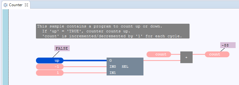
OLT-fields within the FBD-editor
You are able to change the value of a variable within such an OLT-field as follows: Double-click onto the OLT-field and enter a new value in the dialog.
This dialog is identical to the one you are using to change the values within the Values of Variables view. Details: see "Changing the values of variables: writing values to PLC".
For →character string literals the following is additionally valid
: Do not delete the leading/terminating quote character within the input field (these quote characters are not displayed in the OLT-field itself for a STRING-variable but they are needed when entering the value).
More useful information:
Animation of Boolean lines in the FBD-editor
By default, Boolean lines are emphasized within an FBD-editor with →instance context:
Boolean lines are lines that are connected to FBD-elements containing or representing a →variable of →data type BOOL. or a →Boolean literal . The emphasizing of Boolean lines has the following meaning:
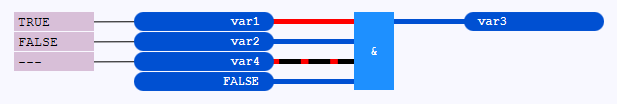
A thick, red line indicates the value TRUE (or an equivalent).
A thick, dark-blue line indicates the value FALSE (or an equivalent).
A thick line dashed in black and red is indicating that no value could be requested for the line. A possible reason for this is that the current state of the application has not been loaded onto the PLC yet. This means for the illustration:: The variables var1, var2 and var3 already exist on the PLC, but not the variable var4.
![]() When animating a Boolean line for a variable, logi.CAD 3 is using the value that exists on the →PLC. However in case of a Boolean literal, logi.CAD 3 is using the value directly from the logic. See "Example: Effect of a changed Boolean literal onto the animation".
When animating a Boolean line for a variable, logi.CAD 3 is using the value that exists on the →PLC. However in case of a Boolean literal, logi.CAD 3 is using the value directly from the logic. See "Example: Effect of a changed Boolean literal onto the animation".
See "Unexpected animation of lines that are connected to a step output " for a known animation problem.
Example: Effect of a changed Boolean literal onto the animation
If you load the application from the above illustration onto the PLC and you change each value FALSE to TRUE afterwards – hence within the OLT-fields and the value field, logi.CAD 3
emphasizes the
Boolean lines from the value field to the AND block as expected.
When animating these Boolean lines,
logi.CAD 3 is using the values for the variables from the PLC and the literal value TRUE from the value field (hence directly from the logic) respectively.
However, the Boolean line from the AND block to the value field containing var3 is not emphasized as it is expected from the functionality of the AND block. The reason for this: The value of the 4th AND input on the PLC is still FALSE.

Solution: Load the current state of the application onto the PLC so that the value of the 4th AND input on the PLC becomes TRUE.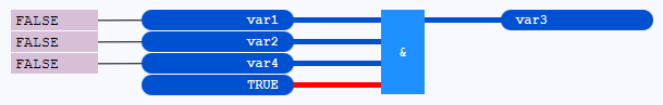
After loading of the application, the initial value FALSE is valid for the variables var1, var2 and var4. So change the value FALSE within the OLT-fields to TRUE again in order to display the desired result of the block within the FBD-editor.
Details on the LD-editor with OLT-fields and animation of Boolean lines
Similar to the FBD-editor, the values of variables incl. the values of function block inputs/outputs are displayed in OLT-fields and the
Boolean lines are emphasized within an LD-editor with
instance context
:
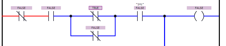
OLT-fields within the LD-editor
You are able to change the value of a variable within an OLT-field as follows: Double-click onto the OLT-field and enter a new value in the dialog.
This dialog is identical to the one you are using to change the values within the Values of Variables view. Details: see "Changing the values of variables: writing values to PLC".
For →character string literals the following is additionally valid
: Do not delete the leading/terminating quote character within the input field (these quote characters are not displayed in the OLT-field itself for a STRING-variable but they are needed when entering the value).
More useful information:
The OLT-fields (showing the value of the variable) are displayed instead of the names of the variables.
If you want to toggle between the values and the names of all variables, press Ctrl+Space and select the command Toggle OLT-Fields.
Here is the above example with the displayed names of the variables: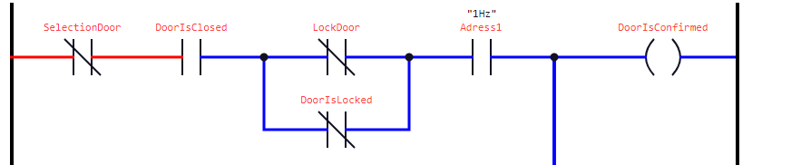
A list with actions for the OLT-fields is provided under "OLT-fields in LD".
Animation of Boolean lines in the LD-editor
See "Animation of Boolean lines" for the meaning of the emphasis .