Coils in LD
According to →IEC-standard: A coil copies the state of the link on its left to the link on its right without modification and it stores an appropriate function of the state or transition of the left link into the associated Boolean
→variable
.
See under "Link elements (lines) and their states in LD" for more information about the state of links.
logi.CAD 3 provides the following types of coils (depending on the →POU type)::
|
Name |
Symbol |
Meaning |
|
Coil |
|
The state of the left link is copied to the associated Boolean variable (= Var1 in the left illustration) and to the right link. |
|
Negated coil |
|
The state of the left link is copied to the right link. The inverse of the state of the left link is copied to the associated Boolean variable (= Var1 in the left illustration). That is, if the state of the left link is OFF, then the state of the associated variable is ON, and vice versa. |
|
Set latch coil |
|
The associated Boolean variable (= Var1 in the left illustration) is set to the ON state when the left link is in the ON state, and remains set until reset by a reset latch coil. |
|
Reset latch coil |
|
The associated Boolean variable (= Var1 in the left illustration) is reset to the OFF state when the left link is in the ON state, and remains reset until set by a set latch coil. |
|
Positive transition sensing coil |
|
The state of the associated Boolean variable (= Var1 in the left illustration) is ON from one evaluation of this element to the next when a transition of the left link from OFF to ON is sensed. The state of the left link is always copied to the right link.
|
|
Negative transition sensing coil |
|
The state of the associated Boolean variable (= Var1 in the left illustration) is ON from one evaluation of this element to the next when a transition of the left link from ON to OFF is sensed. The state of the left link is always copied to the right link.
|


Representation
Symbolic representation:

Each coil provides 3 input fields above the coil symbol:
Description (= [Description] in the upper illustration): Here you are able to enter a description for the coil. If you do not enter any text, this field is hidden. Only when you position the mouse pointer over the coil, the field becomes visible so that you are able to enter a text.
Tag (= [Tag] in the upper illustration): If you do not enter any text, this field is hidden. Only when you position the mouse pointer over the coil, the field becomes visible so that you are able to enter a text.
Associated variable (= Var1 in the upper illustration): Here you are able to associate a variable to the coil. By default, the ENO output is entered as the associated variable.
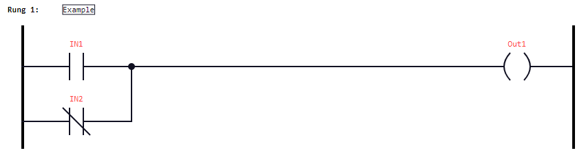
Example for a rung with 2 contacts and one coil: