Functions and function blocks in LD
Use →calls in the →graphical editor →FBD to call a →function or a →function block. A catchall term for functions and function blocks is "→block". If you read about blocks in the logi.CAD 3 user documentation, the description is about functions and function blocks (unless otherwise clearly stated).
A call may get values from other elements via its inputs, the value of the call may be assigned to other elements via its outputs. →Assignments are visualized by lines connecting a call with the other elements.
Representation
Example for a rung with 2 contacts, one coil and the call of the AND block:
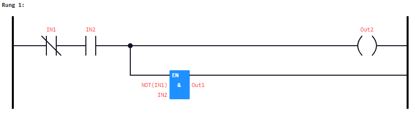
Usually, the input connection point (short: input) of the call is located on the left side and the output connection point (short: output) on the right side. The layout of the call (e.g. the color) is determined by a default layout.![]() Use the interface editor, if you want to change the predefined layout attributes for user-defined blocks (e.g. the orientation of the in-/outputs).
Use the interface editor, if you want to change the predefined layout attributes for user-defined blocks (e.g. the orientation of the in-/outputs).
By default, the EN-input and the ENO-output of the function or function block is connected by a link element. For the other in-/outputs of the function or function block, you are able to enter expressions according to ST . Details: See " Entering an expression for an input/output for a function or function block ".
There are some other peculiarities regarding the representation of functions and function blocks within the LD-editor. As these are the same peculiarities as for the FBD-editor, see "Calls of blocks: functions or function blocks" for these peculiarities.