Calls of blocks: functions or function blocks
Use →calls in the →graphical editor →FBD to call a →function or a →function block. A catchall term for functions and function blocks is "→block". If you read about blocks in the logi.CAD 3 user documentation, the description is about functions and function blocks (unless otherwise clearly stated).
A call may get values from other elements via its inputs, the value of the call may be assigned to other elements via its outputs. →Assignments are visualized by lines connecting a call with the other elements.
It is not possible to insert calls of the following language elements in the FBD-editor:
derived function blocks (= function blocks using the keyword EXTENDS)
abstract function blocks (= function blocks using the keyword ABSTRACT)
Representation
Example for calling the ADD block and the F_TRIG block (incl. assignments by a line
from/to a
→value field
):
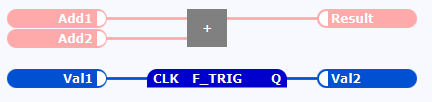
Usually, the input connection point (short: input) of the call is located on the left side and the output connection point (short: output) on the right side. The layout of the call (e.g. the color) is determined by a default layout.![]() Use the interface editor, if you want to change the predefined layout attributes for user-defined blocks (e.g. the orientation of the in-/outputs).
Use the interface editor, if you want to change the predefined layout attributes for user-defined blocks (e.g. the orientation of the in-/outputs).
Peculiarities
More in-/outputs might become visible for an extensible block, if the call is enlarged and the setting Expandable within the interface editor is checked. Example: The AND block is displayed with 2 inputs at least. When it is enlarged, up to 16 inputs are displayed.
A certain number of the inputs of an extensible block must be connected (usually it is 2 inputs). Observe that input variable s of extensible system functions that are not connected get the default →initial value .→In-/out variables within the interface are indicated by the straight line between the input connection point and the output connection point.
Example for calling the user-defined block MyFB (incl. assignments by a value field) that contains an in-/out variable named In_Out1: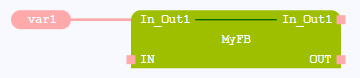
However, if a block with in-out variables has been migrated from logi.CAD/32 to logi.CAD 3, the following is valid: logi.CAD 3 displays the user interface of the block as it is in logi.CAD/32. This means that only the input connection point of the in-out variable is displayed in logi.CAD 3. It is also possible that other variables are located on the opposite position of the input connection point.A value field with the interface for a block is displayed as long as the respective input is not connected with an FBD-element .
Example for the block interface in which the value of the input is assigned to its opposite output (the value is predefined by the 2 value fields within the interface) :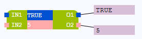
![]() If the FBD-editor and its elements are displayed differently in your logi.CAD 3 version, the system integrator has changed the styles for the FBD-editor. In this case and for information about the changed representation, please contact your system integrator.
If the FBD-editor and its elements are displayed differently in your logi.CAD 3 version, the system integrator has changed the styles for the FBD-editor. In this case and for information about the changed representation, please contact your system integrator.
Actions for calls
Page:Creating a call of a block by dragging from project explorer
Page:Inserting a call of a block or value field into existing lines
Page:Moving FBD-elements
Page:Showing/hiding and editing the instance names of blocks
Page:Setting breakpoints for the calls of blocks and value fields
Page:Creating value fields or calls of blocks by using the content assist in FBD